INTRODUCTION
This section covers the physical installation of the system. It primarily focuses on the parts that are required and how
they should be connected together. Do not connect the mains power or the batteries at this stage; commissioning
the system is covered in the next section of this manual.
Installation should always be performed in accordance with a system plan.
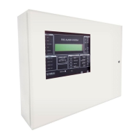
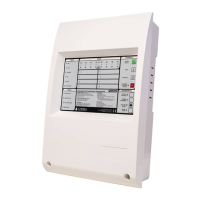
MAIN PANEL
The control panel should be located where access to the internal components is not restricted and where the unit is
not exposed to high levels of moisture, vibration and shock.
Avoid placing the panel in direct sunlight as this may impair programming using the infra-red keypad.
Any metal swarf could damage the PCBs if it is still present when the panel is powered up so it is recommended that
all PCBs are removed from the main box whilst the box is being installed. Make a note of the positions of the PCBs
before removal.
Mains Power Connection
The panel must be earthed.
The LIVE connection must be made to the fused input on the power supply module. This input will also have a BLACK
or BROWN wire leading into the power supply unit.
The connector with a BLUE wire leading into the power supply unit is the NEUTRAL.
These are detailed in the relevant following sections. Most connections are made from the J-NET-CON.
WARNING: observe ESD precautions when handling the PCBs.
Other Main Panel connections
INSTALLATION
ELECTRO-STATIC SENSITIVE DEVICES (ESD)
TAKE SUITABLE ESD PRECAUTIONS WHEN REMOVING OR
INSTALLING PRINTED CIRCUIT BOARDS.
22
Manufacturers of Fire Detection Equipment
INSTALLATION & COMMISSIONING MANUAL REVISION 4.0 05/2013
JUNO NET - NETWORKABLE ADRESSABLE PANEL
globalfire.pt