WR1000-UM-251–01–9380 3 – 14
3. DISASSEMBLY AND REASSEMBLY
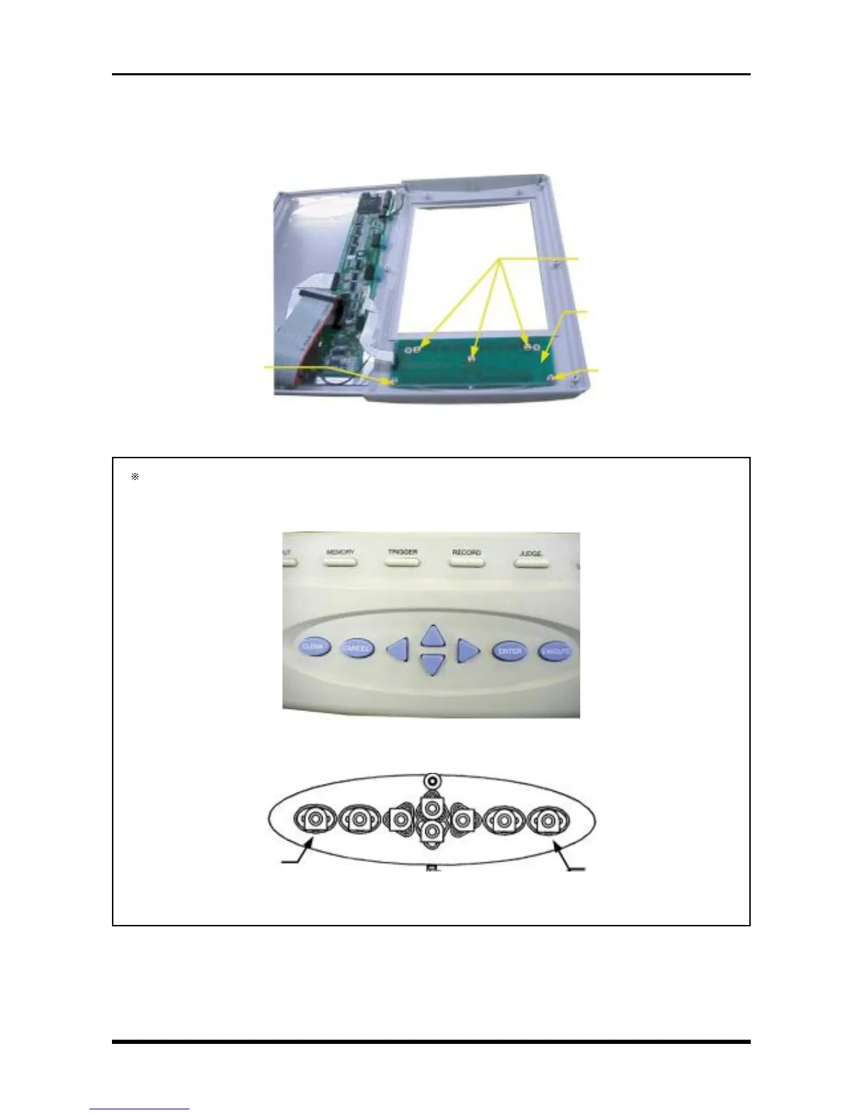
(2) Remove the Conditions panel key board
a. Remove the LCD shield plate (see Subsection 3.3.1, “Replacing the Inverter Board”).
b. Remove the LCD (see Subsection 3.3.2, “Replacing the LCD Panel”).
c. Remove the five screws then remove the Conditions panel key board.
Fig. 3-3-17
During reassembly, confirm that the keytops on the Conditions panel match are arranged according
to the photograph below before securing the Conditions panel key board. (Fig. 3-3-19 shows the rear
view.)
Fig. 3-3-18
Fig. 3-3-19
M3L6 tapping screws
Conditions panel key board
M3L6 tapping screws
M3L6 tapping screws
EXECUTE
CLOSE