WR1000-UM-251–01–9380 6 – 10
6. INSPECTION AND CHECK PROCEDURES
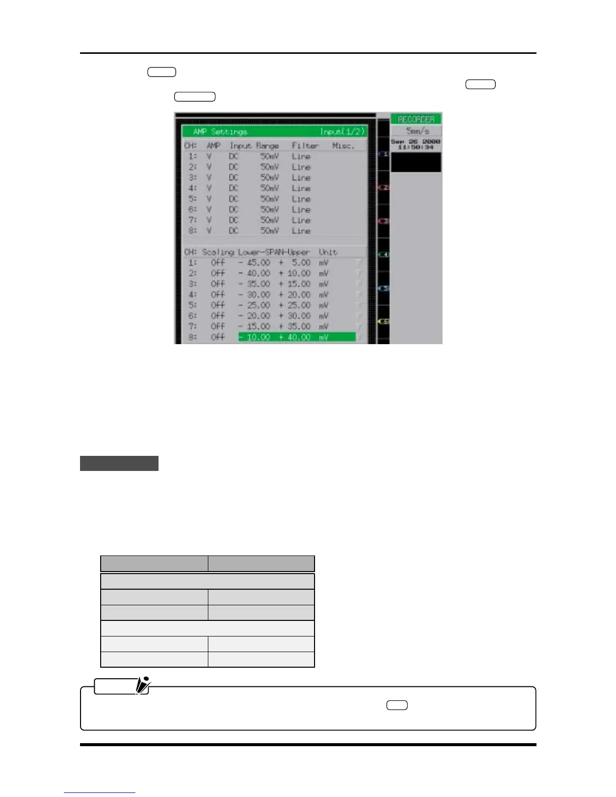
(3) Press the
INPUT
key on the Conditions panel to display the AMP Settings window shown below. Use
the arrow keys to move the cursor to the desired parameter, then use the arrow keys,
ENTER
key, jog/
shuttle dial, and
EXECUTE
key to enter the following settings.
Fig. 6-2-11. AMP Settings window
AMP V or M
Input DC
Range 50mV (if AMP = V) or 20mV (if AMP = M)
Filter Off
Scaling Off
Lower-SPAN-Upper Specify an appropriate pitch that will enable simultaneous viewing of eight lines
Measurement
(1) Turn on the printer.
(2) Use short terminals to short the input terminals of all channels.
(3) Measure the width of each line printed by the recording operation and check that its width is within the
rated range.
Table 6-2-4
NOTE
To measure Channels 9 through 16, press the amp control panel’s
SEL
key to switch the channel
group displayed, then resume measurement.
RANGE setting At 200-mm oscillation
V amp
50 mV within 1 mm
5 V within 1 mm
M amp
20 mV within 0.75 mm
2 V within 0.75mm