GETTING STARTED
17
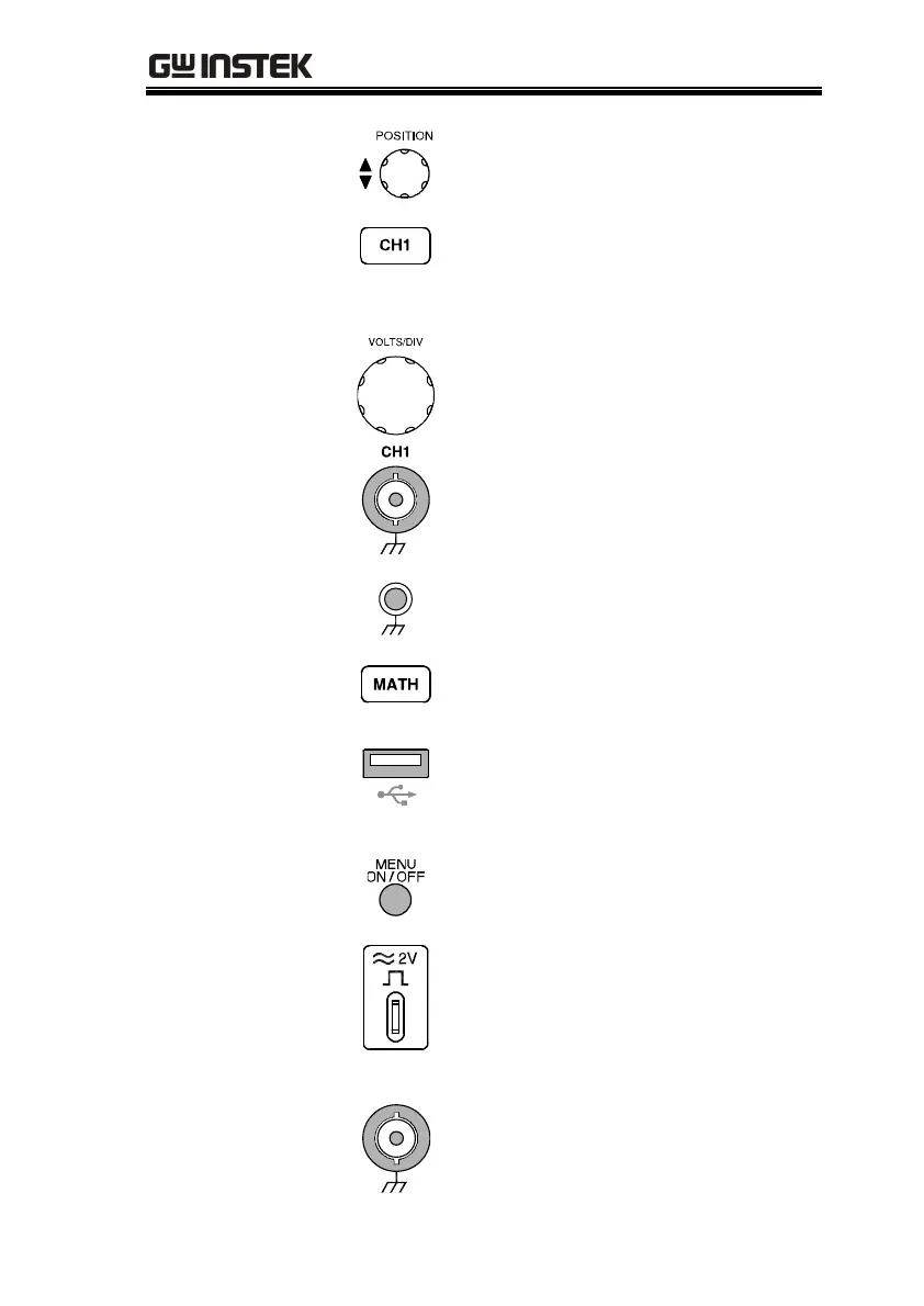
Vertical position
knob
Sets the vertical position of
waveforms (page102).
Channel menu
key
Configures the vertical scale and
coupling mode for each channel
(page102).
Volts/Div knob
Selects the vertical scale (page102).
Input terminal
Accepts input signals. Input
impedance: 1MΩ±2%.
Ground terminal
Accepts the DUT ground lead for
common ground.
Math key
Configures and runs math
operation (page64).
USB host port
TypeA, 1.1/2.0 compatible. Prints
out display image (page146) or
transfers data (page119).
Menu On/Off key
Shows or hides menu in the LCD
display (page94).
Probe
compensation
output
Outputs 2Vp-p, square signal for
probe compensation (page159) or
demonstration. Can be used for
generic purpose (page53) as well.
External trigger
input
EXT TRIG
For 2ch model only. Accepts
external trigger signal (page106).
Input impedance: 1MΩ±2%.

 Loading...


