157
Figure 67 Cable binding example 1
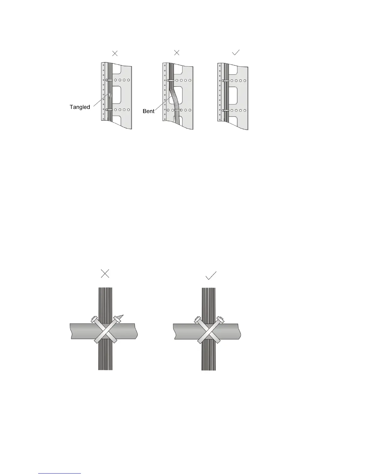
• Different cables (power, signal, and PGND cables) should be routed and bound separately rather
than together in the rack. If they are close to each other, you can route them in cross-shape. For
parallel routing, the space between power cable and signal cable should be no less than 30 mm
(1.18 in) .
• The cable management bracket and cable routing slot inside and outside the rack should be
smooth and without sharp edges or tips.
• The metal cable management hole should have a smooth and fully rounded surface or wear an
insulating bush.
• Use the right type of ties to bind the cables. Do not bind cables with joined ties. The following types
of ties are available currently: 100 × 2.5 mm (3.94 × 0.10 in), 150 × 3.6 mm (5.91 × 0.14 in), 300
× 3.6 mm (11.81 × 0.14 in), 530 × 9 mm (20.87 × 0.35 in), and 580 × 13 mm (22.83 × 0.51 in).
• Cut the extra parts of the ties neatly after binding the cables, leaving no sharp or angular tips. See
the following figure:
Figure 68 Cable binding example 2
• Bind the cables wherever cable bending cannot be avoided. However, the cable ties cannot be
placed inside the bending area in case of the likelihood of cable core break due to excessive stress.
See the following figure.

 Loading...


