38
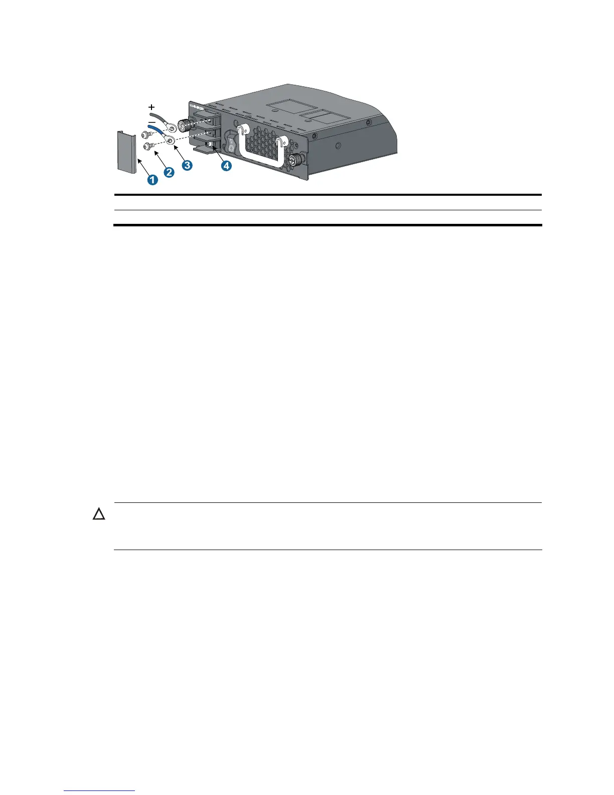
Figure 30 Connect the PSR320-D/PSR650-D power cable
1: Protection cover 2: Screws
3: DC wiring terminals 4: Grounding sign
Connecting the PSR1400-D power cable
Follow these steps to connect the PSR1400-D power cable:
Step1 Loosen the captive screws on the protection cover with a Phillips screwdriver and remove the protection
cover. There are two flat washers, one spring washer, and one M6 fastening nut from inside to outside
on each wiring terminal.
Step2 Loosen the captive nuts on four wiring terminals with a M6 socket wrench, and remove the captive nut,
spring washer, and one flat washer in turn from each wiring terminal.
Step3 Connect the end of the blue DC power cable marked with – to the negative terminal (–) on the power
module.
Step4 Connect the end of the black DC power cable marked with + to the RTN (+) terminals on the power
module.
Step5 Put the flat washer and spring washer on the wiring terminal in turn and screw up the captive nut with
the M6 socket wrench. Repeat this step for the other three terminals.
Step6 Put the protection cover on the wiring terminals and faster the captive screws.
Step7 Connect the other ends of the DC power cables to the wiring terminals that provide a power supply to
the switch.
CAUTION:
When connecting the DC power cable to the DC wiring terminals, make sure that the – end of the circui

 Loading...


