6 - Maintenance
167
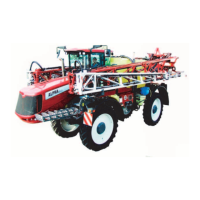
Speed Sensor for pump
The speed transducer, measuring rounds per minute (r.p.m.), is located at the inner side of the PTO shield. This sensor is an
inductive type, which requires metallic protrusions to pass by it to trigger a signal.
If the sensor is exchanged, it must installed accurately to function.
Adjustment
1. Adjust the air gap (A) between sensor tip and pump part is set by turning the nuts on the support bracket for the
sensor.
The air gap (A) must be set to 1 mm (+0.3/-0.0 mm). Use a feeler gauge or similar tool to verify.
2. Verify transducer function on the controller:
• HC 6500 / ISOBUS VT: Monitor the menu [4.5.4.9.6 PTO pump frequency].
Standard regulation
DynamicFluid4 regulation
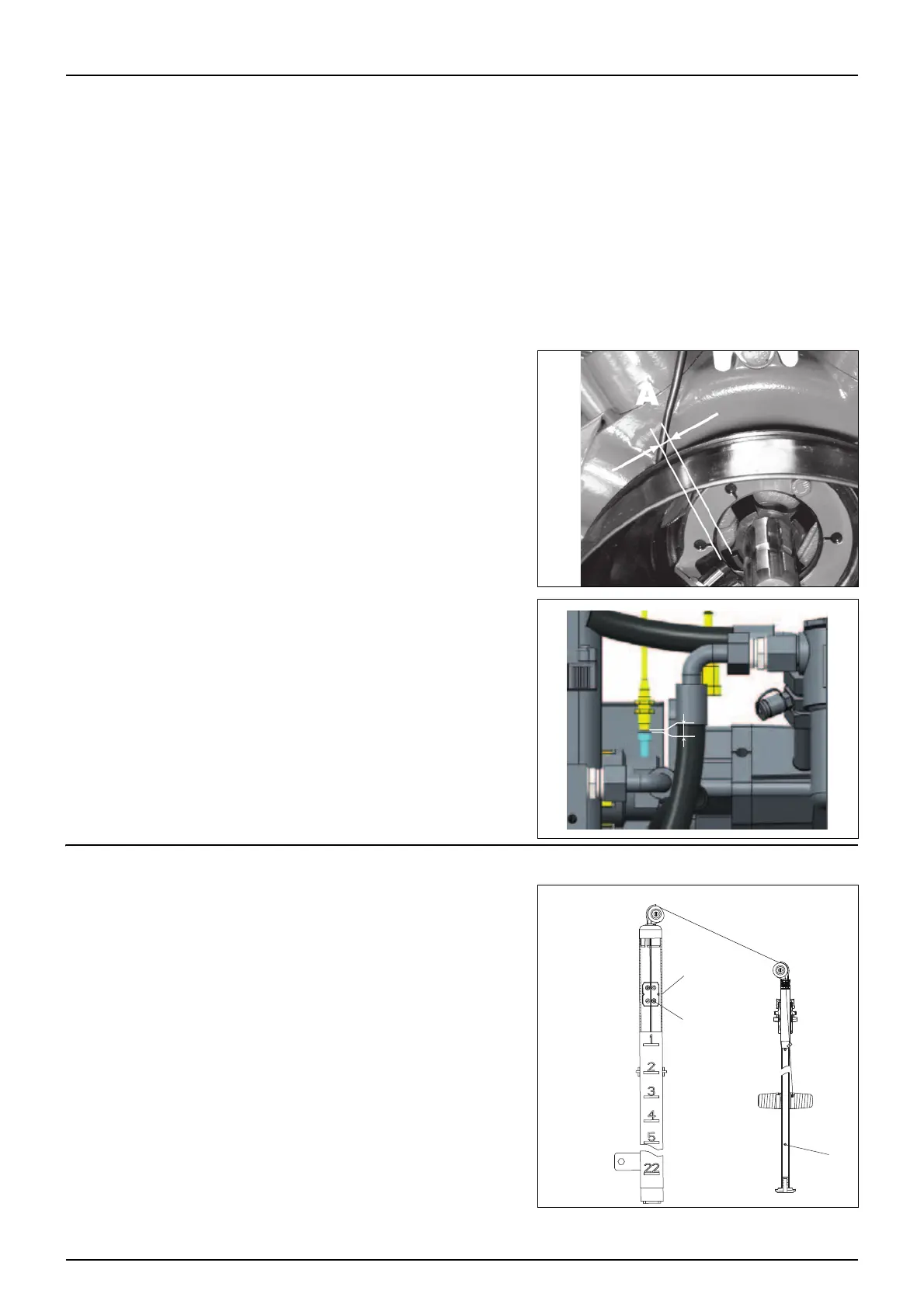
Level Indicator Adjustment
The level indicator reading should be checked regularly. When the tank
is empty, the float should lie on the stop pin (D) of the rod, and the O-
ring on the indicator should be positioned at the top position line (A).
μ
ATTENTION! The wire guide wheels should be directed so they
follow the direction of the wire
If any deviation is found, do the following:
1. Pull out the plug (B).
2. Loosen screws (C).
3. Adjust the length of the cord, until it reads correctly.
4. Push the plug (B) back into place.
 Loading...