3 - Description
51
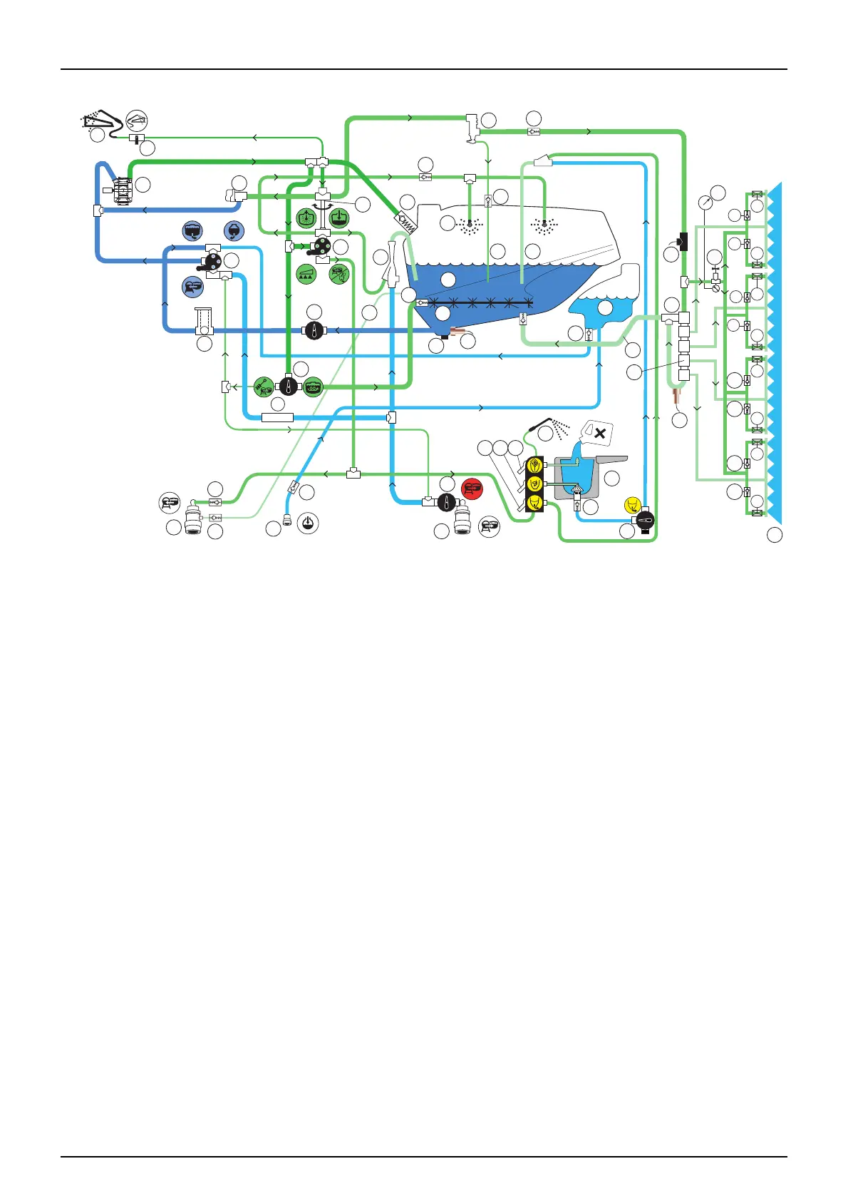
Diagram - Liquid system with optional extras
1. Suction SmartValve
2. Pressure SmartValve
3. Agitation/Cleaning valve
4. Chemical container cleaning valve
5. TurboDeflector ON/OFF valve
6. TurboFiller suction ON/OFF valve
7. Pump
8. Main tank
9. EasyClean filter
10. Rinse Tank
11. Spray valve
12. CycloneFilter
13. TurboFiller
14. Lance for cleaning TurboFiller
15. Safety valve
16. Internal tank cleaning nozzles
17. Agitation tube
18. Return line for boost function
19. TurboFiller to tank tube
20. RinseTank coupler
21. DynamicFluid4 pressure regulation valve
22. One-way valve
23. Drain valve
24. Sprayer boom
25. Flowmeter
26. Bypass valve
27. Sensor for pressure gauge
28. Distribution valves
29. Return from distribution valves
30. Main tank gauge sensor
31. Pressure draining coupler
32. FastFiller coupler
33. External cleaning device (optional)
34. External cleaning ON/OFF valve (optional)
35. TurboFiller vacuum valve ON/OFF
36. External fast filling ON/OFF valve (optional)
37. Boost valve
38. Ejector
39. Main tank suction ON/OFF valve
40. Boom prime restrictor (optional)
41. Pressure relief line
42. Boom prime pressure control valve (optional)
43. Pressure gauge for BoomPrime (optional)
44. Suction In-line filter
34
33
36
31
22
22
38
41
39
22
32
20
30
23
17
22
10
22
1
2
15
16
22
8
18 19
22
21
7
3
9
11
14
6
13
22
35
5 4
44
28
27
22
22
26
24
22
12
40
40
22
22
40
40
22
22
40
40
40
40
22
22
43
42
29
25
 Loading...