Network Video Recorder User Manual
40
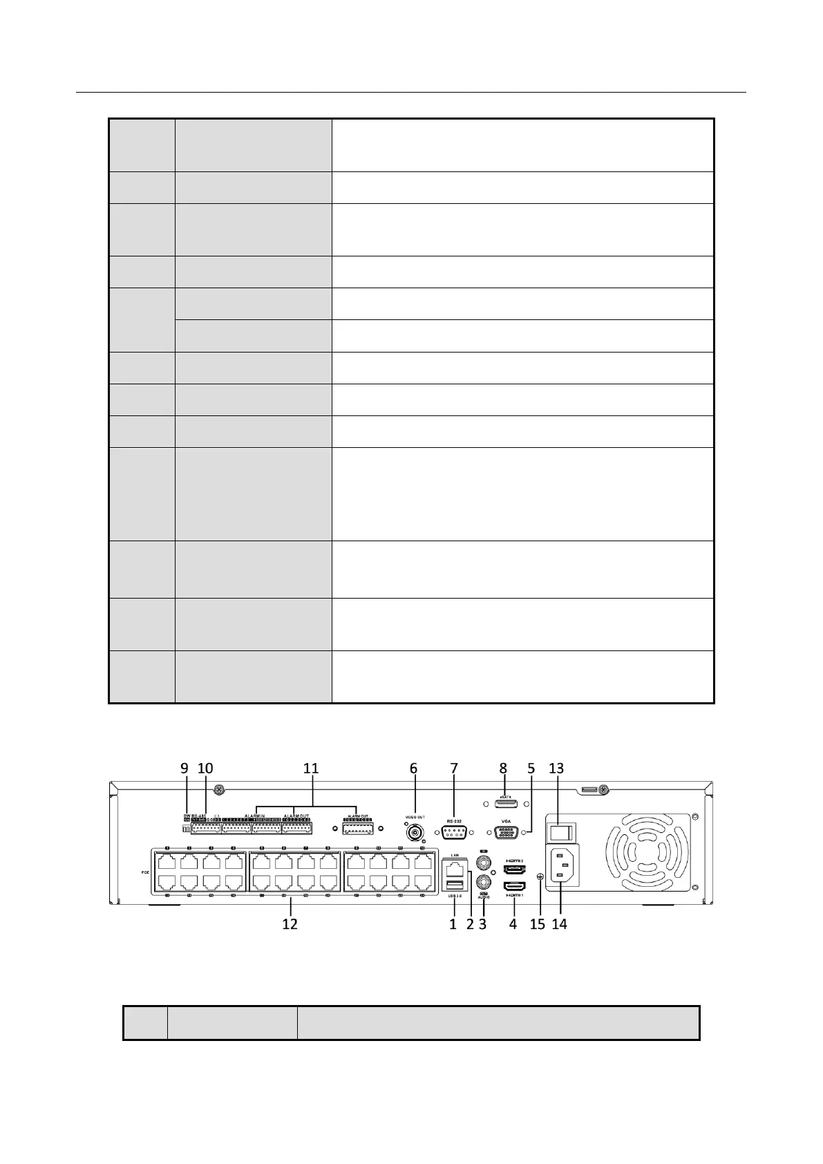
1.4.4 DS-8600NI Series
Figure 1-15 DS-8600NI Series
Table 1-10 Panel Description
Universal Serial Bus (USB) ports for additional devices
such as USB mouse and USB Hard Disk Drive (HDD).
Connector for RS-232 devices.
DB9 connector for VGA output. Display local video
output and menu.
Half-duplex connector for RS-485 devices.
Connector for alarm input.
Connector for alarm output.
Ground (needs to be connected when NVR starts up).
Switch for turning on/off the device.
100V to 240VAC power supply.
Network Interfaces
with PoE function
(supported by
DS-7700NI-I4/P)
Network interfaces for the cameras and to provide
power over Ethernet.
Up position is not terminated.
Down position is terminated with 120Ω resistance.
BNC connector for audio output. This connector is
synchronized with CVBS video output.
eSATA Interface
(Optional)
Connects external SATA HDD, CD/DVD-RM.
 Loading...