B 9302 (0507)
139
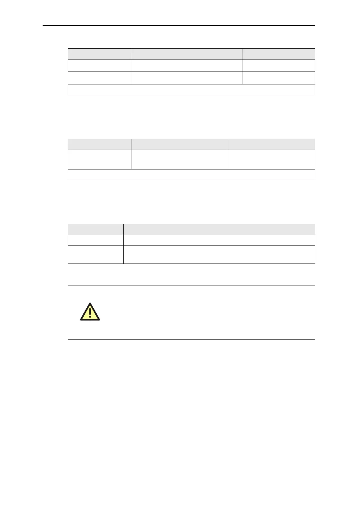
2.3 Output 5 VDC
2.4 Connection WD
2.5 I/O Bus
Refer also to: Supply, feeding and distribution of the 24 V system voltage, see assembly kit,
wiring diagram.
Connection Wire and connection Use
XG.4: +5 V
YE 2 x 2.5 mm
2
, Faston 6.3 x 0.8 from central rack
XG.12: GND
GN 2 x 2.5 mm
2
, Faston 6.3 x 0.8 from central rack
GN = Color code green YE = Color code yellow
Table 3: Output 5 VDC
Connection Wire and connection Use
XG.15:1
GY 0.5 mm
2
, wire end ferrule from central rack and to fur-
ther I/O racks
GY = Color code gray
Table 4: Connection WD
Connection Procedure
XD.1 Plug in BV 7032 and connect it with the I/O subrack before
XD.2 Plug in BV 7032 of the following I/O subrack on the according I/O bus
or plug in bus termination module F 7546 (at the last I/O subrack)
Table 5: I/O Bus
With installation of the assembly kit a conductive connection to the
frame or a separate earth connection has to be installed according to
the EMC requirements.
Connection PE earth: Faston 6.3 x 0.8 mm.
Pay attention for the manufacturers information concerning detaching
and replugging of the Faston connectors!
 Loading...