B 9302 (0507)
138
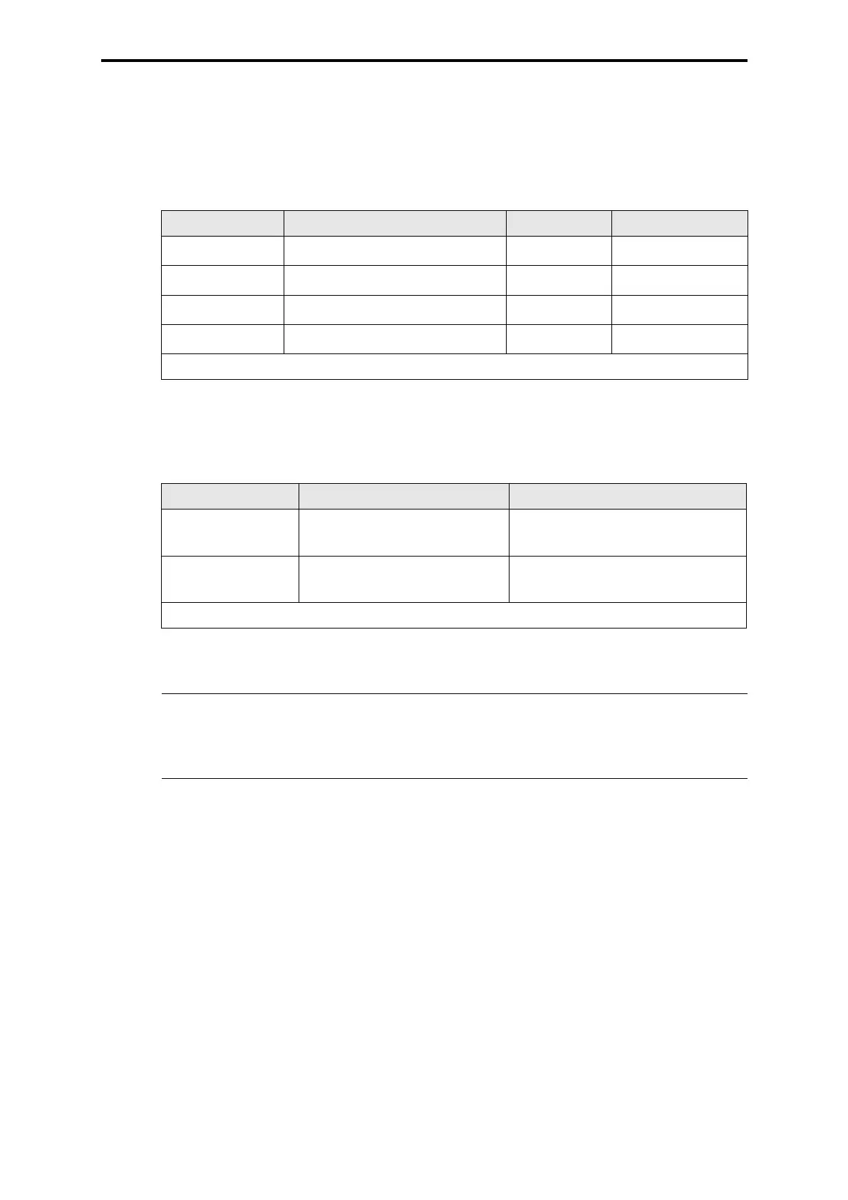
2 Wiring of the assembly kit connections
Wirings to be done by the user:
2.1 Supply 24 VDC
2.2 Output 24 VDC
Connection Wire and connection Fusing Use
XG.7 (L+)
RD 2.5 mm
2
, Faston 6.3 x 0.8
max. 16 A gL F 7133, slot 21
XG.8 (L+)
RD 2.5 mm
2
, Faston 6.3 x 0.8
max. 16 A gL F 7133, slot 20
XG.9 (L+)
RD 2.5 mm
2
, Faston 6.3 x 0.8
max. 16 A gL F 7133, slot 19
XG.10 (L+)
RD 2.5 mm
2
, Faston 6.3 x 0.8
max. 16 A gL F 7133, slot 18
RD = Color code red
Table 1: Supply 24 VDC
Connection Wire and connection Use
XG.3 (L+) RD 1.5 mm
2
, Faston 6.3 x 0.8 from central rack and to further I/O
racks
XG.11 (L-) BK 2 x 2.5 mm
2
,
Faston 6.3 x 0.8 (see note)
Reference pole L-
RD = Color code red BK = Color code black
Table 2: Output 24 VDC
Note
To be wired to the central L- bus bar with at least 2 x 2.5 mm
2
BK. If
output modules with 2-pole connection to the actuators are used
depending on the load up to 4 x 2.5 mm
2
BK wiring is necessary.
 Loading...