B 9361 (0507)
144
2 Wiring of the assembly kit
Wirings to be done by the user (refer to "Assembly kit, wiring diagram"):
2.1 Supply 24 VDC
2.2 Output 5 VDC
** for distances > 2 m: wire cross section 6 mm
2
2.3 Output 24 VDC
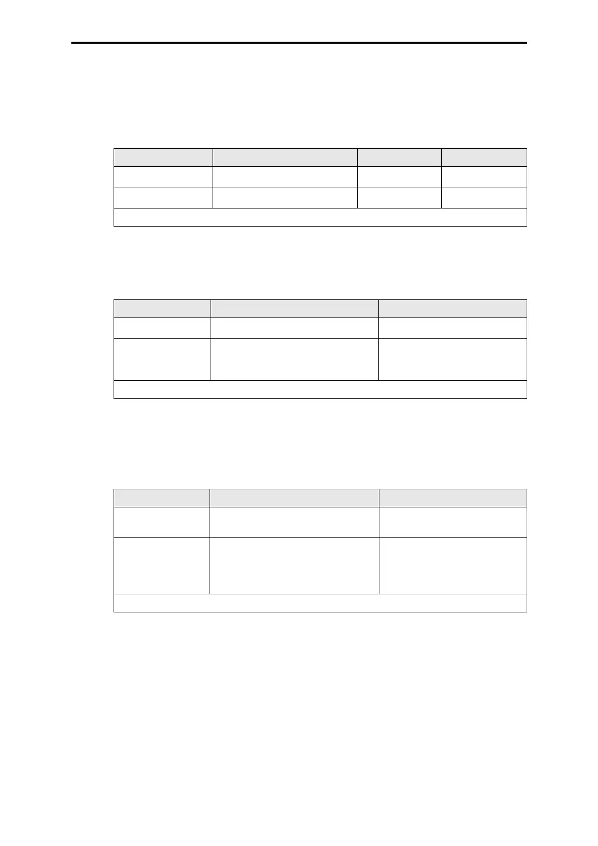
Connection Wire and connection Fusing Use
XG.21/22/23:2 (L+)
RD 2.5 mm
2
, Faston 6.3 x 0.8
max. 16 A gL PS1...PS3
XG.21/22/23:1 (L-)
BK 2.5 mm
2
, Faston 6.3 x 0.8
Reference pole
RD = Color code red BK = Color code black
Table 1: Supply 24 VDC
Connection Wire and connection Use
XG.2: +5 V
YE 2 x 2.5 mm
2
, Faston 6.3 x 0.8**
Supply I/O subrack (B 9302)
XG.3: GND
GN 2 x 2.5 mm
2
, Faston 6.3 x 0.8**
Supply I/O subrack (B 9302), to
be connected with the GND of
the central rack
GN = Color code green YE = Color code yellow
Table 2: Output 5 VDC
Connection Wire and connection Use
XG.24:2 (L+)
RD 1.5 mm
2
, Faston 6.3 x 0.8
Supply fuse monitoring and IO-
CON in the I/O subrack
XG.25:2 (L+)
RD 1.5 mm
2
, Faston 6.3 x 0.8
Supply fuse monitoring and IO-
CON in I/O subrack for 2nd I/O
bus (B 5222-2, B 5223-2,
B 5232-2 and B 5233-2 only)
RD = Color code red
Table 3: Output 24 VDC