F 3349 (0641)
257
Additional technical data
Current input WD 1 mA
Monitored switching time max. 200 μs (without extension by
the function block)
Internal voltage drop max. 2 V at 500 mA load
Admissible line resistance max. 11
Ω
max. lamp load 10 W
max. inductivity 1 H
max. capacity 100 μF
Output leakage current max. 500 μA
Operating points of the line moinitoring
Line short-circuit 0.7...0.8 A
Line break 2...8 mA
Reaction of the module to errors
• Module error:
All outputs are switched off.
• Line error:
If an external line break or a short-circuit is detected, the module only makes an annun-
ciation to the corresponding central module.
At a short-circuit and an overcurrent (> 2 A per channel) the overcurrent tripping is acti-
vated after 50 ms at the latest. For smaller overloads (> 0.7 A per channel) the reaction
time can last up to several seconds.
At line errors the channel of the module is reconnected again after approx. 4.5 se-
conds.
• The error codes for the module are shown in the display of the corresponding central
module. For further information see operating system manual.
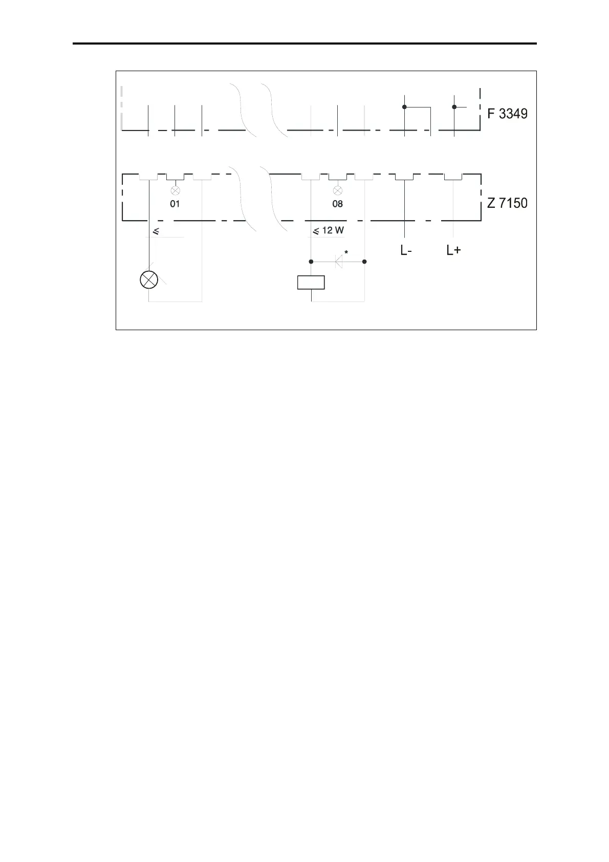
2-pole connection of the loads required!
Figure 4: 2-pole connection
* required with
inductive load
10 W
z28
z12
b16
z4
b18
b2
z32
b32
z2