F 6214 (0606)
277
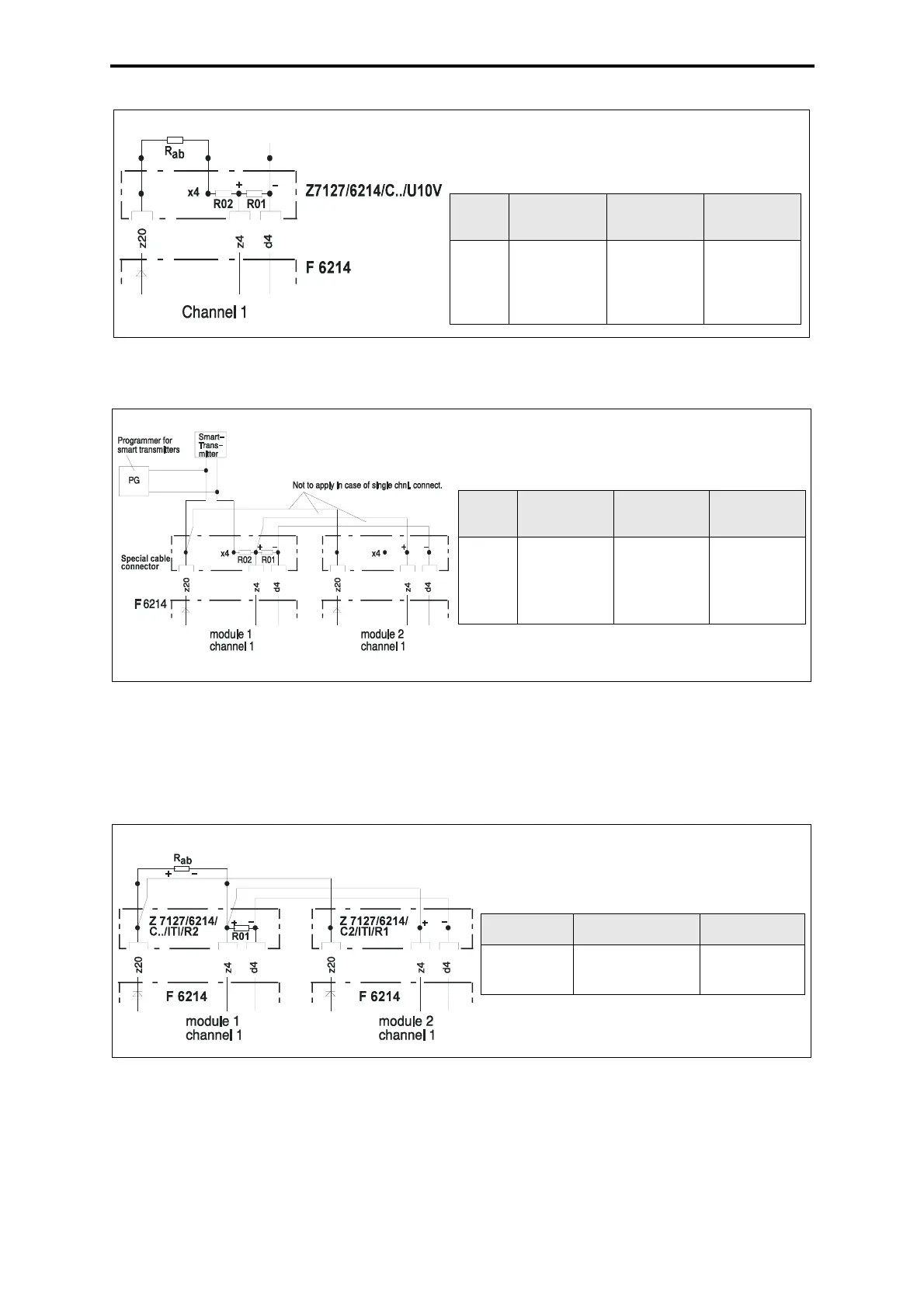
Figure 13: Voltage input 0...10 V
Figure 14: Connection of smart transmitters
Not used inputs, redundant connection
All examples are for channel 1
Install the resistors outside the cable connectors on terminals.
Figure 15: Active/passive transmitter 0/4...20 mA
Voltage input 0...10 V
Resistors for channels 1...4 (R
ab
= terminating re-
sistor for not used channels):
Resi-
stor
R01, 03, 05,
07
R02, 04, 06,
08
R
ab
Value
part
no.
38.3 k
Ω,
1%
00 0751383
332 kΩ,
00 0751334
1 MΩ,
5%
00 0471105
Connection of smart transmitters
Resistors for channels 1...4 (R
ab
= terminating
resistor for not used channels):
Resi-
stor
R01, 03,
05, 07
R02, 04,
06, 08
R
ab
Value
part
no.
50
Ω,
0.05%
00 0710500
220 Ω,
5%
00 0471221
3.3 kΩ,
5%
00 0471332
Active/passive transmitter 0/4...20 mA
Resistors for channels 1...4 (R
ab
= terminating
resistor for not used channels):
Resistor R01, 03, 05, 07
R
ab
Value
part no.
50
Ω, 0.05%
00 0710500
3.3 kΩ, 5%
00 0471332
 Loading...