B 4235 / H41q-MS (0605)
68
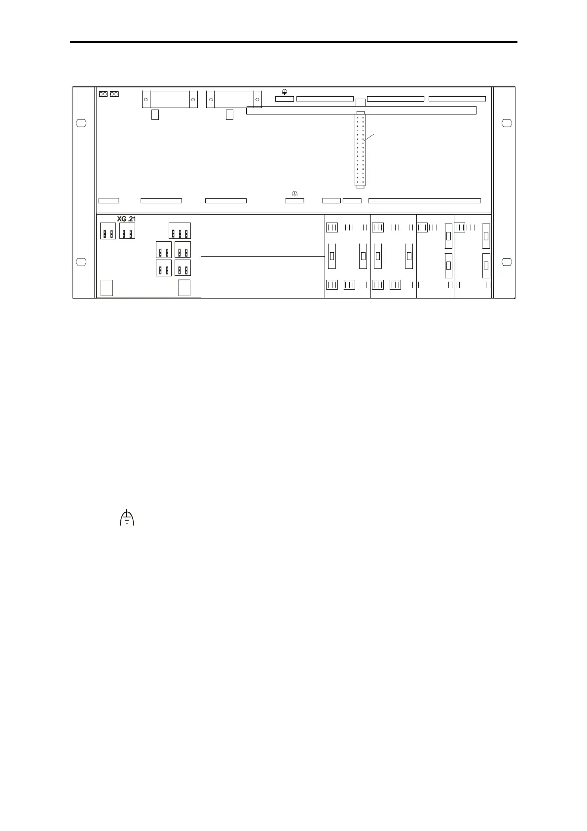
4.5 Connections on the rear
Figure 3: Connections on the rear of the system rack K 1409
4.5.1 Wiring ex works
XD .1 Jumper plug Z 6007 (Combination of the separated I/O buses,
single channel system H41q-MS)
XG .1, XG .2 Supply L+ for the power supply module
Reference pole: XG .9 (L-)
XG .3, XG .4, XG .5 Potential distributor, free disposal of
XG .9 L- for the power supply module
XG .10 Watchdog signal (not active at H41-MS)
XG .11 Watchdog signal from CU1
XG .12 Watchdog signal for I/O modules (not active at H41-MS)
XG .13 Watchdog signal for I/O modules
PE (earth)
Connections of the additional modules Z 6011, Z 6018, Z 6013:
XG. 21 refer to
XG. 22, XG .23 wiring of the assembly kit, wiring diagram
S1, S2 for switching off the buffer batteries G1, G2
delivery state: buffer batteries are switched off!
4.5.2 Wiring by customer
XG .6: 1 - 13 L+ for I/O modules (slots 1 to 13)
13 single connections, see also connection XG .14
XG .14: 1 - 13 Reference potential L- for I/O modules
Slots 1 - 13, see also connection XG .6
XG .24, XG .25 Supply 24 VDC, see assembly kit, wiring diagram (L+, L-)
Z1009
XG .10
XG .9
S2
XG.2 XG.1
on
G2
XG .11
S1
HIMA H41
on
G1
Z6013Z6013
6
XG .22
2
1
F2
45
31
F1
2
F2 F1
789 4
XG .23
657 8
XG .25
Z6011
F2
312
Z6011
314 2
F1
91
XG .24
768 176
3 4
F2
F1
8
XG .14
XG .13XG .12
XD .1
XG .3 XG .4 XG .5
XG .6
Z 6007
13121110987654321
L+ NG L+ NG
L- 1 1
791113
L-22
5
33
3
44
1
WD2 WD1
81012 6 4 2
Z 6018
1a 1b
2 3
7 8
9 10
11 12
13 14
4 5 6