B 4235 / H41q-MS (0605)
69
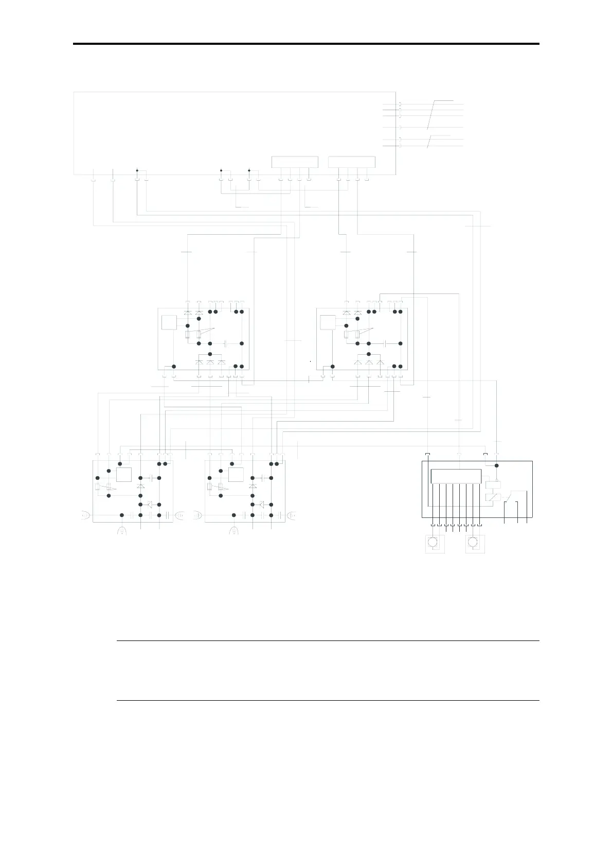
4.6 Assembly kit, wiring diagram
Figure 4: Assembly kit, wiring diagram
Lü-Ü =Fan monitoring
Si-Ü = Fuse monitoring
Note The assembly kit is fully wired for a possible extension to redundant
systems. For extension to redundant I/O buses remove jumper plug
Z 6007 (see data sheet H41q-HR, H41q-HRS).
Z 1009
G. 6: 1
G. 6: 2
G. 6: 3
XG. 6: 13
XG. 14
XG. 14
...
see note “Supply 24 VDC”
RD 1 mm²
Feeding PS1
L+ L+ L–
XG.1 XG.2 XG.9 XG.13 XG.12 XG.11 XG.101234 1234
Watchdog C 1U Watchdog C 2U
GY 0.5 mm
2
GY 0.5 mm
2
BK 1.5 mm
2
GY 0.5 mm
2
GY 0.5 mm
2
GY 0.5 mm
2
GY 0.5 mm
2
RD 1.5 mm
2
XG.22
8 9 222 111
Si-Ü
L+ L–
1,6 A
Z 6013
XG.22
33 5 6 7444
F1F2
XG.23
8 9 222 111
Si-Ü
L+ L–
1.6 A
XG.23
33 5 6 7444
F1F2
RD 1 mm
2
GY 0 5mm
2
RD 1 mm
2
GY 0.5 mm
2
BK 1 mm
2
BK 1 mm
2
BK 0.5 mm
2
RD 0.5 mm
2
GY 0.5 mm
2
XG.25
78446 55
5
Si-Ü
L+ L–
4 A
XG.25
32 1
F1F2
Z 6013
Z 6011
GY 0.5 mm
2
GY 0.5 mm
2
Supply 24 VDC
XG.24
78446 55
5
Si-Ü
L+ L–
4 A
XG.24
32 1
F1F2
Z 6011
Supply 24 VDC
Feeding PS2
G.21
Lü-Ü
&
Z 6018
XG.21
2311
546
7 8 91011121314
L+ from feeding and
current distribution
L- from feeding and
current distribution
L+ slot 1
L+ slot 2
L+ slot 3
L+ slot 13
L- slot
L- 1 to 13
Fuse and
fan monitoring
. . .
4 Fans
K 9212