B 4237-1/-2 / H41q-HS/HRS (0605)
83
4.1.3 Supply 5 VDC
The 5 VDC power supply does not have to be wired separately as it is already installed as part
of the subrack.
The 5 VDC power is used for the CPU, the control of the interfaces and the I/O modules. It is
generated by 24 VDC / 5 VDC power supply module type F 7130A. The subrack is equipped
with two power supply modules. The power supply modules are switched in parallel. If one of
them fails, the other supplies the PES.
The 5 VDC output voltage of the power supply module (for the CPU, I/O and the interfaces)
are monitored on the central module checking undervoltage, overvoltage or failure.
In case of a faulty power supply module the operating system of the CPU informs the user pro-
gram via a system variable.
In case of a 5 VDC system power failure a lithium battery on the central module buffers the
hardware clock and sRAM on the central module.
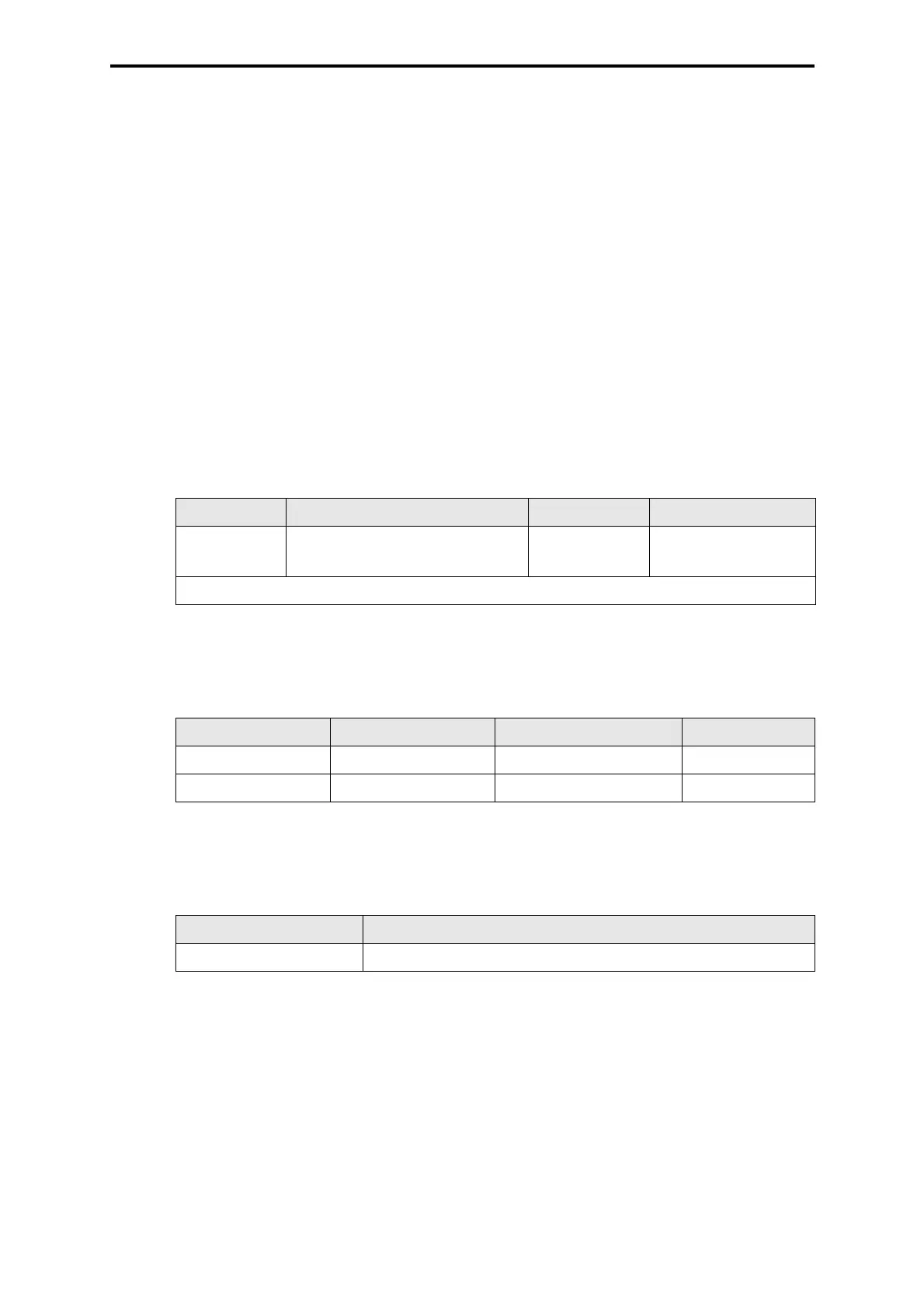
4.2 Connection of the monitoring loop (for fuses and fans)
4.3 Internal fuses
4.4 Connections of the WD to H41q-HRS / B 4237-2
4.5 Backplane bus
Central module CU and I/O modules are connected via the backplane bus.
The jumper plug Z 6007 on connection XD .1 combines the separated I/O buses. For the single
channel system this is mandatory (H41q-HS). With redundant I/O bus (H41q-HRS) the jumper
plug Z 6007 at the backplane of the subrack is not installed.
Connection Wire and connection Fusing Use
XG.21:4/5/6
GY 0.5 mm
2
, Faston 2.8 x 0.8
max. 4 A slow
blow
Floating NO/NC con-
tact for signaling
GY = Color code gray
Table 2: Connection of the monitoring loop
Position Size Dimension HIMA part no.
Z 6011 4 A slow blow 5 x 20 mm 57 0174409
Z 6013 1.6 A slow blow 5 x 20 mm 57 0174169
Table 3: Internal fuses
Connection Procedure
XG.12 and XG.13 Remove override between both connections
Table 4: Connections of the WD