B 4237-1/-2 / H41q-HS/HRS (0605)
82
4 Wiring of the assembly kit
The assembly kit is already wired for operation. Wirings have still to be done by the user (op-
tional modules, see "Assembly kit, wiring diagram").
4.1 Current distribution within the assembly kit
4.1.1 HIMA devices for current distribution
It is recommended to use the HIMA supplies and current distributions:
4.1.2 Supply 24 VDC
The supply voltage 24 VDC may be fed two times to the system H41q-HS/HRS. See also cat-
alog H41q/H51q, chapter 3.3, The Input/Output Level, 24 VDC Supply and Distribution.
With installation of the assembly kit a conductive connection to the
frame or a separate earth connection has to be installed according to
the EMC requirements.
Connection PE earth: Faston 6.3 x 0.8 mm.
Pay attention for the manufacturers information concerning detaching
and replugging of the Faston connectors!
K 7212 redundant feeding up to 35 A total current, with 2 decoupling diodes and 2 net-
work filters, with fusing of up to 12 single circuits with circuit breakers or
K 7213 redundant feeding up to 35 A total current, with fusing of up to 12 single cir-
cuits with circuit breakers or
K 7214 redundant feeding up to 150 A total current, with fusing of up to 18 single cir-
cuits with circuit breakers or
K 7215 redundant feeding up to 150 A total current, with fusing of up to 18 single cir-
cuits with circuit breakers, graphical display.
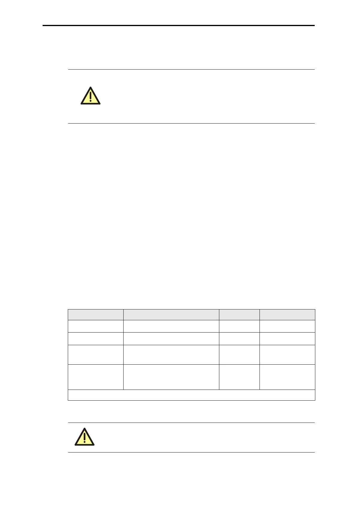
Connection Wire and connection Fusing Use
XG.24/25:2 (L+)
RD 2.5 mm
2
, Faston 6.3 x 0.8
max. 16 A PS1, PS2
XG.24/25:1(L-)
BK 2.5 mm
2
, Faston 6.3 x 0.8
Reference pole L-
XG.14 (L-)
BK 2 x 2.5 mm
2
, Faston 6.3 x 0.8
(see note)
Reference pole L-
XG.6 (L+)
RD 1 mm
2
, Faston 2.8 x 0.8
13 single connections
max. 4 A
slow blow
see wiring diagram
RD = Color code red BK = Color code black
Table 1: Supply 24 VDC
Connection XG.14: To be wired to the central L- bus bar with at least 2 x
2.5 mm
2
BK. If output modules with 2-pole connection to the actors are
used depending on the load up to 4 x 2.5 mm
2
BK wiring is necessary.
 Loading...