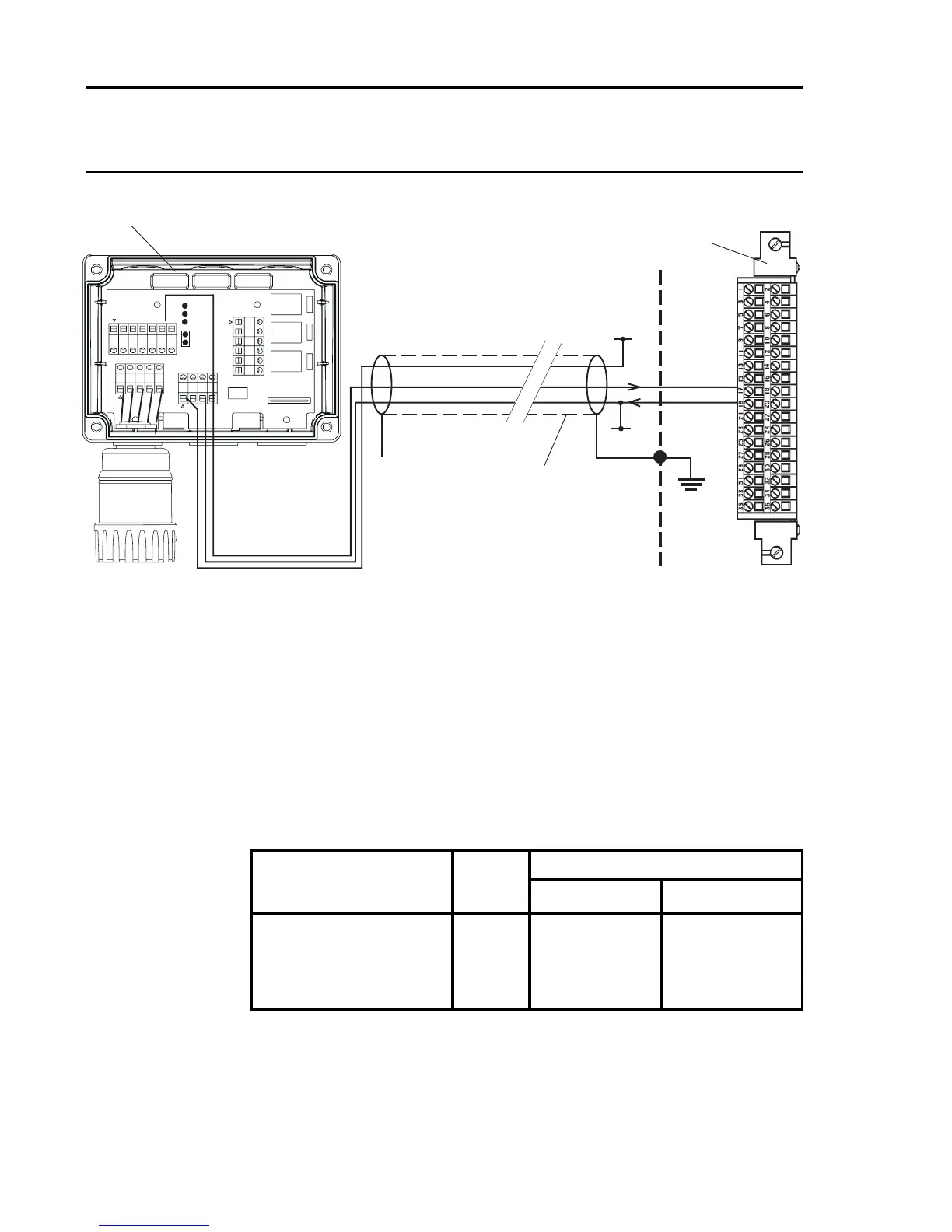
Notes: 1. Where the sensor is earthed locally, either to the stud or through
the sensor casing or mounting, to avoid earth loops the screen
sheath should only be connected at one end, i.e. the sensor
or at the relay/interface card.
2. The above diagram shows the sensor connections for Channel
1. Channels 2, 3 and 4 connections are similar and their pin
connection numbers are shown below:
Channel Sensor Connection
01 NS
Quad Relay 1 17 19
Interface Connections 2 18 20
3 23 25
4 24 26
Three Wire Control Card Current Sink, Transmitter Current
Source Connection for Opus/Lifeline II
(Signal Returned to 0V)
* 24V supply may be obtained
from either the cabinet or a
separate eld supply

 Loading...


