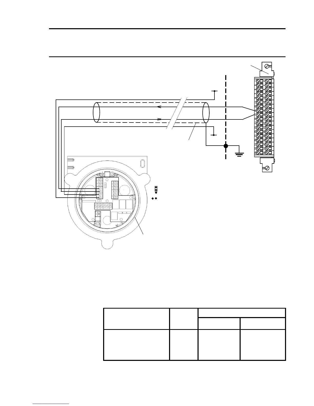
Note: 1. The Apex Transmitter should be earthed locally. The
transmitter is earthed through the Earth Stud, to avoid
earth loops the screen sheath of the cable
should only be connected at the transmitter.
2. The above diagram shows the sensor connections for
Channel 1. Channels 2, 3 and 4 connections are similar and
their pin connection numbers are shown below:
Channel Transmitter Connection
S 01
Quad Relay 1 15 17
Interface Connections 2 16 18
3 21 23
4 22 24
Four Wire Isolated Signal Input, Transmitter Connection for
Apex
S
01
Screened
Cable
Arrows Indicate
Direction of Loop
Current Flow
+24V
4 - 20mA(-)
4 - 20mA(+)
0V
Quad Relay Interface Card
05704-A-0121
15
17
Cabinet
Protective
Earth
+24V*
0V*
Apex Transmitter
SK4
(Comms
and
Power)
Apex
1
2
3
4
5
6
7
Apex Link
Settings:
J4
J5
* 24V supply may be obtained
from either the cabinet or a
separate eld supply

 Loading...


