SCANNER SAFETY AND LOCAL CONTROLS
2.5 Head Movement Monitoring and Control
The scanner is equipped with various switches that monitor and control head movement.
Table 15 lists and describes the switches.
Table. 15. Head Movement Monitoring and Control Switches
Provides a permanent fixed reference to the motor controller software to monitor
the head position relative to encoder counts. Identifies approximate mid-beam
position of head movement
Limit (forward and reverse)
Indicates that the head has reached the configured horizontal-movement limit
Crash (forward and reverse)
Stops all scanning and alerts the computer that a head has reached a hard stop
This is an operator push button that will disable the scanning motor controller and
any active sensors, for example, basis weight shutters will close, lasers will turn off
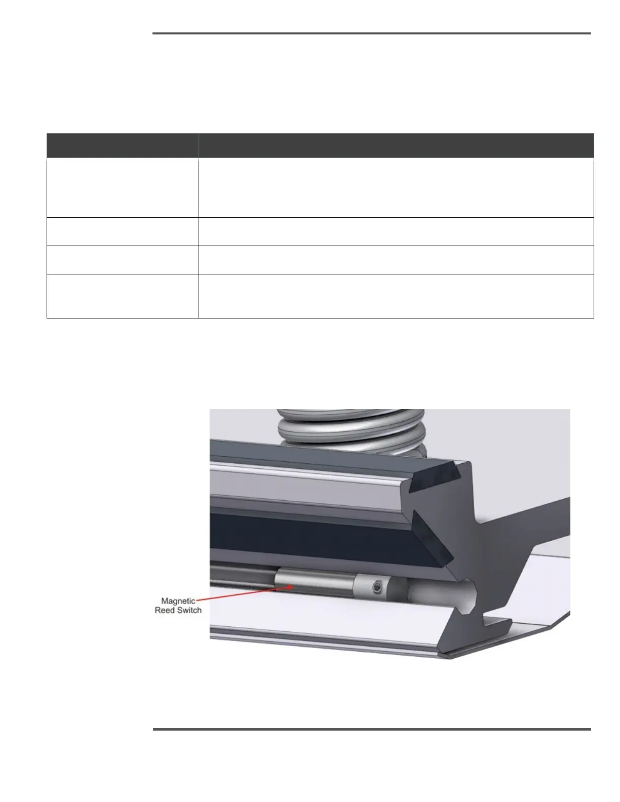
Preset, limit, and crash switches are mounted to the upper and lower head carriage tracks
(see Figure 58 and Figure 59). Switches are triggered by magnets mounted in the upper
and lower carriages. These switches can be moved by loosening the locking set screw, and
sliding to a new location.
Fig. 58. Track Mounted Switches (limit, crash, and preset)

 Loading...