60 IFP-300 Series Manual — P/N LS10145-001SK-E:C 4/6/2022
Control Panel Installation Remote Station Applications
3. Map the group to activate constant on from the zone event.
4. Program the output group characteristics as non-silenceable and reverse polarity.
Using the SD500-ARM Addressable Relay Module
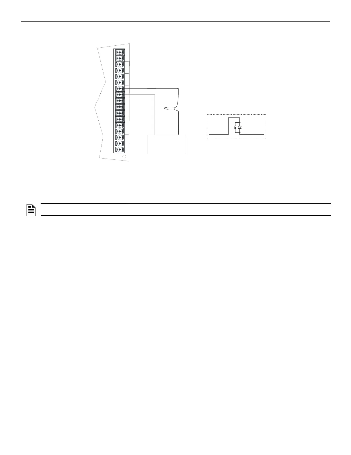
When the SD500-ARM is wired for polarity reversal, it reports alarm and trouble events to a remote site. Alarms will override trouble condi-
tions and it will not be possible to reset the remote indicator until the condition is cleared and the control panel is reset. Relay 2 must be pro-
grammed for Alarm (default).
–
+
TROUBLE
NC C NO
RELAY1
NC C NO
RELAY2
NC C NO
NAC1 NAC2 NAC3 NAC4
+ - + - + - + -
remote indicator
black white
black white
7644-L8
7644-L8
1k
Figure 4.50 Polarity Reversal Connection Using the 7644-L8
NOTE: additional SD500-ARM modules must be added, if you need to transmit supervisories or trouble conditions. Use Relay 1 to transmit
supervisory conditions. Use the trouble relay to transmit trouble conditions.

 Loading...


