222 HC900 Process & Safety Controller User and Installation Manual Revision 6
21 April 2017
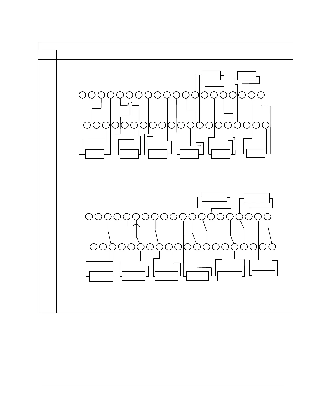
1 2 3 7 8 94 5 6 10 11 12 13 17 18 1914 15 16 20
21 22 23 27 28 2924 25 26 30 31 32 33 37 38 3934 35 36 40
Input 1 Input 2
Input 3
Input 4
Input 6
Input 7
Input 8
3 wire
RTD
3 wire
RTD
3 wire
RTD
3 wire
RTD
3 wire
RTD
3 wire
RTD
Input 5
3 wire
RTD
3 wire
RTD
Note: You must set
switches 1- 8 for RTD.
1 2 3 7 8 94 5 6 10 11 12 13 17 18 1914 15 16 20
21 22 23 27 28 2924 25 26 30 31 32 33 37 38 3934 35 36 40
1 2 3 7 8 94 5 6 10 11 12 13 17 18 1914 15 16 20
21 22 23 27 28 2924 25 26 30 31 32 33 37 38 3934 35 36 40
Input 1 Input 2
Input 3
Input 4
Input 6
Input 7
Input 8
3 wire
RTD
3 wire
RTD
3 wire
RTD
3 wire
RTD
3 wire
RTD
3 wire
RTD
Input 5
3 wire
RTD
3 wire
RTD
Note: You must set
switches 1- 8 for RTD.
Figure 101 – Three-wire RTD input connections
1 2 3 7 8 94 5 6 10 11 12 13 17 18 1914 15 16 20
21 22 23 27 28 2924 25 26 30 31 32 33 37 38 3934 35 36 40
Input 1 Input 2
Input 3
Input 4
Input 6
Input 7
Input 8
2 wire
RTD/OHMS
2 wire
RTD/OHMS
2 wire
RTD/OHMS
2 wire
RTD/OHMS
2 wire
RTD/OHMS
2 wire
RTD/OHMS
Input 5
2 wire
RTD/OHMS
2 wire
RTD/OHMS
Note:
You must set switches 1- 8
for Ohms.
Note:
Install jumper
wires:
3-23
6-26
8-28
12-32
13-33
16-36
17-37
20-40
1 2 3 7 8 94 5 6 10 11 12 13 17 18 1914 15 16 20
21 22 23 27 28 2924 25 26 30 31 32 33 37 38 3934 35 36 40
1 2 3 7 8 94 5 6 10 11 12 13 17 18 1914 15 16 20
21 22 23 27 28 2924 25 26 30 31 32 33 37 38 3934 35 36 40
Input 1 Input 2
Input 3
Input 4
Input 6
Input 7
Input 8
2 wire
RTD/OHMS
2 wire
RTD/OHMS
2 wire
RTD/OHMS
2 wire
RTD/OHMS
2 wire
RTD/OHMS
2 wire
RTD/OHMS
Input 5
2 wire
RTD/OHMS
2 wire
RTD/OHMS
Note:
You must set switches 1- 8
for Ohms.
Note:
Install jumper
wires:
3-23
6-26
8-28
12-32
13-33
16-36
17-37
20-40
Figure 102 – Two-wire RTD or ohm input connections

 Loading...


