Revision 6 HC900 Process & Safety Controller User and Installation Manual 233
21 April 2017
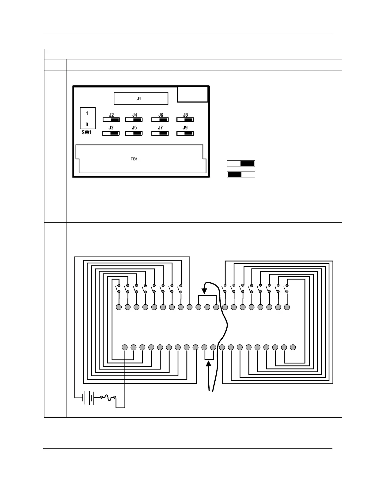
16 Point DC Digital Input
Set/verify jumper positions as shown for the 16 point digital input module.
Module Removal / Insertion Under Power (RIUP) is supported by turning off Switch SW1 to allow removal of
the module from the rack without causing an arc. Please see page 83 for more details.
ATTENTION: SW1 only disconnects the positive terminal, not both sides of the DC power.
See page 240 for RTP internal schematic.
Note: SDC+ in the wiring figure below refers to power that is disconnected from these screw terminals when
switch SW1 is open (0).
1 2 3 4 5 6 7 8 9 10 11 12 13 14 15 16 17 18 19 20
21 22 23 24 25 26 27 28 29 30 31 32 33 34 35 36 37 38 39 40
IN1
IN2
IN3
IN4
IN5
IN6
IN7
IN8
IN9
IN10
IN11
IN12
IN13
IN14
IN15
IN16
DC Supply
IN1+
IN2+
IN9+
IN10+
IN5+
IN6+
DC
-
IN3+
IN4+
IN7+
IN8+
DC
-
DC
-
DC
-
IN11+
IN12+
IN13+
IN14+
IN15+
IN16+
SDC+
SDC+
DC+
SDC+
SDC+
SDC+
SDC+
SDC+
SDC+
SDC+
SDC+
SDC+
SDC+
SDC+
SDC+
SDC+
SDC+
SDC+
SDC+
SDC+
Install jumper wires

 Loading...


