1 2 3 4 5 6 7 8 9 10 11 12 13 14 15 16 17 18 19 20
21 22 23 24 25 26 27 28 29 30 31 32 33 34 35 36 37 38 39 40
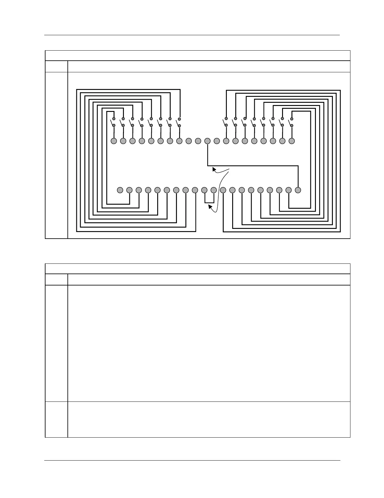
IN1
IN2
IN3
IN4
IN5
IN6
IN7
IN8
IN9
IN10
IN11
IN12
IN13
IN14
IN15
IN16
IN1+
IN2+
IN9+
IN10+
IN5+
IN6+
COM
IN3+
IN4+
IN7+
IN8+
COM
COM
COM
IN11+
IN12+
IN13+
IN14+
IN15+
IN16+
IN1
-
IN2
-
IN3
-
IN4
-
IN5
-
IN6
-
IN7
-
IN8
-
COM
COM
IN9
-
IN10
-
IN11
-
IN12
-
IN13
-
IN14
-
IN15
-
IN16
-
COM
NA
Install jumper wires
ATTENTION: RTP and cables are intended for permanent installation within their own enclosure.
ATTENTION: The RTP combines the two groups of 8 inputs into one group of 16.
Mount RTP cable assembly to HC900 Controller (Figure 96).
Remove appropriate key tabs from terminal board to allow mating with the module. See page 85.
Connect desired cable to 16 point DC DI module at controller. Choose from:
900RTC-L010 Remote Terminal Low Voltage Cable Assembly, 1.0 meters long
900RTC-L025 Remote Terminal Low Voltage Cable Assembly, 2.5 meters long
900RTC-L050 Remote Terminal Low Voltage Cable Assembly, 5.0 meters long
Install 16 point DC DI module label into the module connector cover.
Connect shield drain wire to the grounding bars at the base of the HC900 rack. All field-wiring
shields must be grounded as described in the shield grounding section (page 81).

 Loading...


