Mount RTP cable assembly to HC900 Controller (Figure 96).
Remove appropriate key tabs from terminal board to allow mating with the module. See page 85.
Connect desired cable to 16 point Contact DI module at controller. Choose from:
900RTC-L010 Remote Terminal Low Voltage Cable Assembly, 1.0 meters long
900RTC-L025 Remote Terminal Low Voltage Cable Assembly, 2.5 meters long
900RTC-L050 Remote Terminal Low Voltage Cable Assembly, 5.0 meters long
Install 16 point contact DI module label into the module connector cover.
Connect shield drain wire to the grounding bars at the base of the HC900 rack. All field-wiring
shields must be grounded as described in the shield grounding section (page 81).
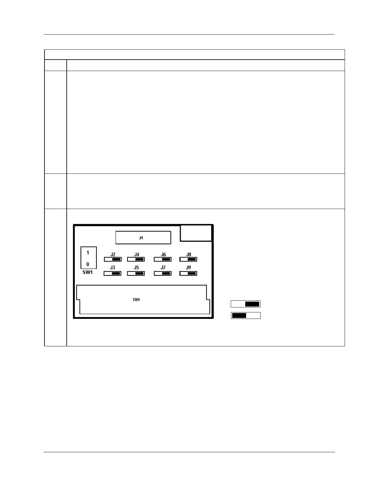
SW1 is not used. Module RIUP is not affected by using the RTP.
See page 240 for RTP internal schematic.

 Loading...


