21 22 23 24 25 26 27 28 29 30 31 32 33 34 35 36 37 38 39 4021 22 23 24 25 26 27 28 29 30 31 32 33 34 35 36 37 38 39 40
1 2 3 4 5 6 7 8 9 10 11 12 13 14 15 16 17 18 19 20
IN1+
IN5+
IN2+
IN3+
IN4+
IN6+
IN7+
IN9+
IN10+
IN8+
IN1
-
IN5
-
IN2
-
IN3
-
IN4
-
IN6
-
IN7
-
IN8
-
1 2 3 4 5 6 7 8 9 10 11 12 13 14 15 16 17 18 19 20
IN1+
IN5+
IN2+
IN3+
IN4+
IN6+
IN7+
IN9+
IN10+
IN8+
IN1
-
IN5
-
IN2
-
IN3
-
IN4
-
IN6
-
IN7
-
IN8
-
RTP A for
inputs 1 to 10
1 2 3 4 5 6 7 8 9 10 11 12 13 14 15 16 17 18 19 20
21 22 23 24 25 26 27 28 29 30 31 32 33 34 35 36 37 38 39 4021 22 23 24 25 26 27 28 29 30 31 32 33 34 35 36 37 38 39 40
IN11+
IN12+
IN13+
IN14+
IN11
-
IN12
-
IN15+
IN16+
IN15
-
IN13
-
IN14
-
IN16
-
IN15+
IN16+
IN15
-
IN13
-
IN14
-
IN16
-
IN9
-
IN10
-
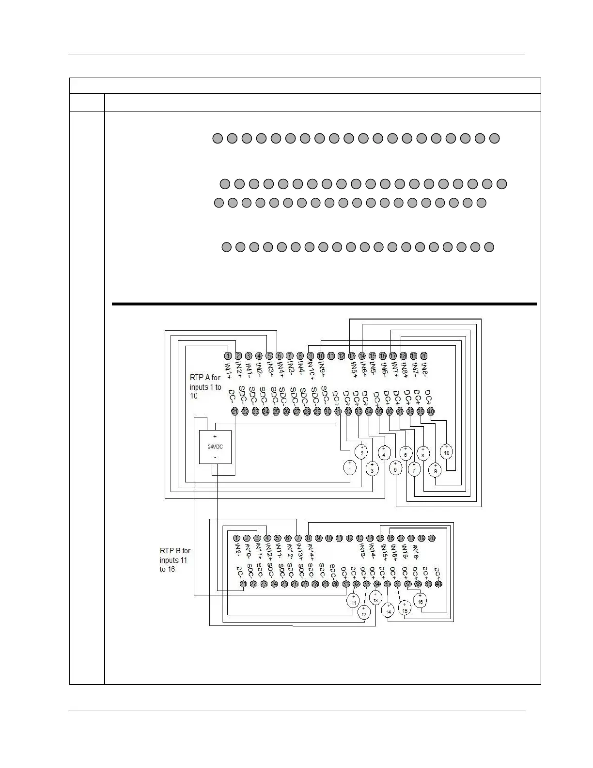
RTP B for
inputs 9 to 16
Notice that Inputs 9 and 10 are connected across RTP A and RTP B.
Figure 104 - Voltage input connections
Not shown: recommended external current loop fuses.
Additionally, on RTP A connect the following terminals: 3-22, 4-23, 7-24, 8-25, 15-26, 16-27, 19-29, 20-30
On RTP B connect the following terminals: 1-22, 2-23, 5-24, 6-25, 13-26, 14-27, 17-28, 18-29
Figure 105 - Current connections with 2-wire transmitter

 Loading...


