248 HC900 Process & Safety Controller User and Installation Manual Revision 6
21 April 2017
32 Point DC Digital Output
ATTENTION: RTP and cables are intended for permanent installation within their own enclosure.
ATTENTION: 32 point DC Digital Output is limited to 6A per RTP and 0.5A per output.
Mount RTP cable assembly to HC900 Controller (Figure 96).
Remove appropriate key tabs from terminal board to allow mating with the module. See page 85.
Connect terminal block end of desired cable assembly to 32 point Digital Output module at
controller. Choose from:
900RTC-3210 Remote Terminal Cable assembly, 1.0 meters long
900RTC-3225 Remote Terminal Cable assembly, 2.5 meters long
Install 32 point DC DO label into the module connector cover.
Connect both shield drain wires to the grounding bars at the base of the HC900 rack. All field-wiring
shields must be grounded as described in the shield grounding section (page 81).
Latch to rail. See page 253.
Connect cables to RTPs. Cables are marked “RTP A” and “RTP B.” In step 4, RTP A will be wired to
outputs 1-16, RTP B to outputs 17-32. You can write on the RTPs’ labels to distinguish them.
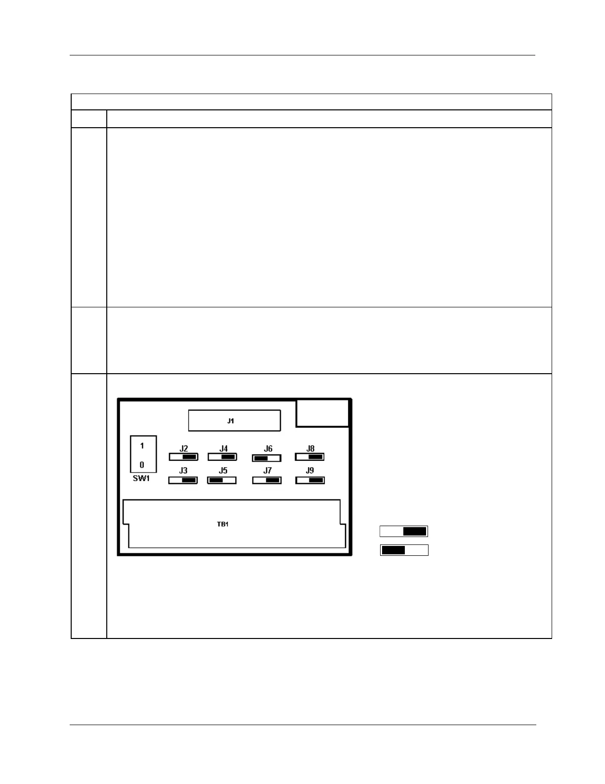
Set/verify jumper positions on each RTP as shown.
Module Removal / Insertion Under Power (RIUP) is supported by turning off Switch SW1 to allow removal of
the module from the rack without causing an arc. See page 83.
ATTENTION: SW1 opens current loop on the ground side so that RIUP of module is possible, but
voltage is still present on the positive side at RTP and module terminals.
See page 252 for RTP internal schematic.

 Loading...


