SCSI and I/O 8-43
Write Protection
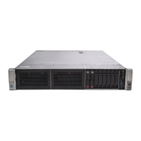
To configure the drive for write protection, install the jumper across secondary Option connector pins 7-8
as shown in Figure 8-18. To disable write protection, remove the jumper.
Figure 8-18. Write Protection
Delayed Spin-Up
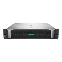
To have the drive spin-up at power on, install the jumper across pins 1 and 2 of the secondary Option
connector, as shown in Figure 8-19.
Figure 8-19. Delayed Spin-Up.
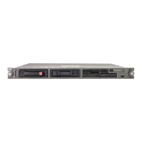
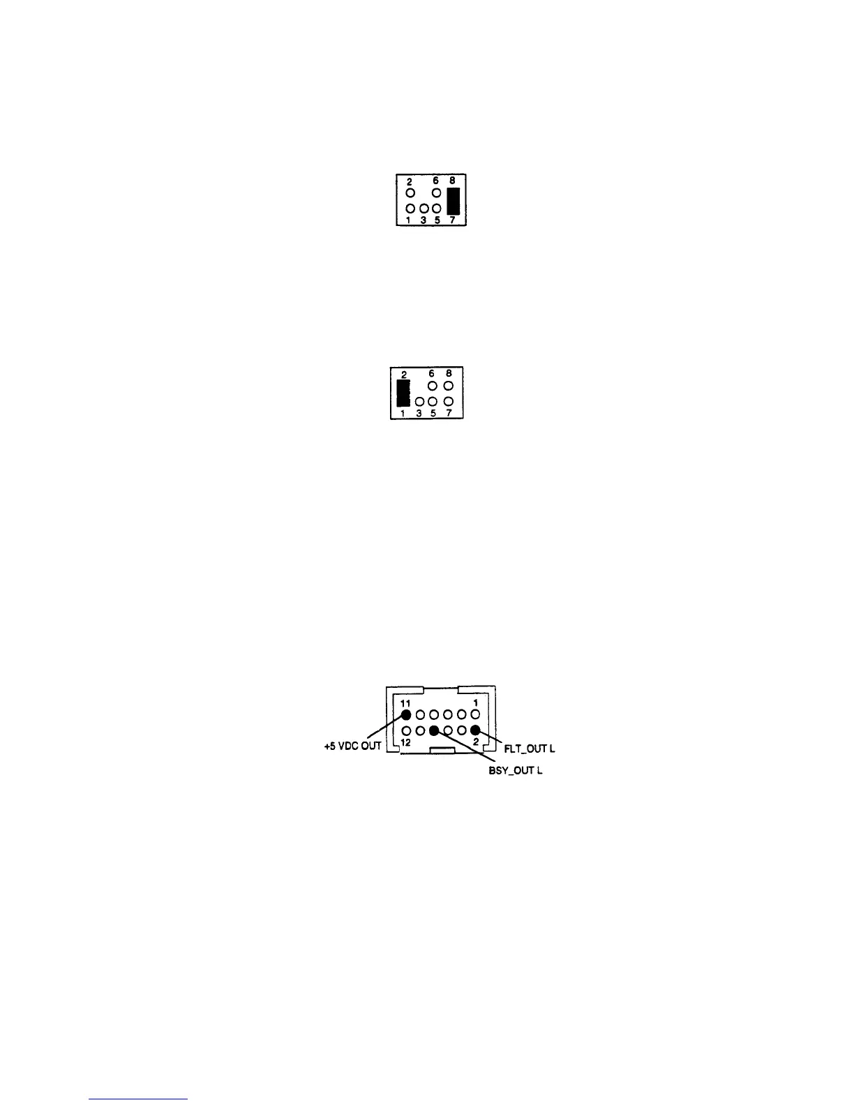
Remote Busy and Fault LEDs
Busy and Fault status can be monitored remotely by connecting a remote (external) Busy and remote Fault
display LED to the 12-pin Option connector.
• Remote Busy LED: Connect the cathode side of the remote Busy LED to pin 8, BSY_OUT L.
Connect the anode side of the LED to pin 11, +5VDC OUT.
• Remote Fault LED: Connect the cathode side of the remote Fault LED to pin 2, FLT_OUT L.
Connect the anode side of the LED to pin 11, +5VDC OUT.
These pin positions are shown in Figure 8-20.
Figure 8-20. Remote Busy and Fault Display Connections.

 Loading...