8-48 SCSI and I/O
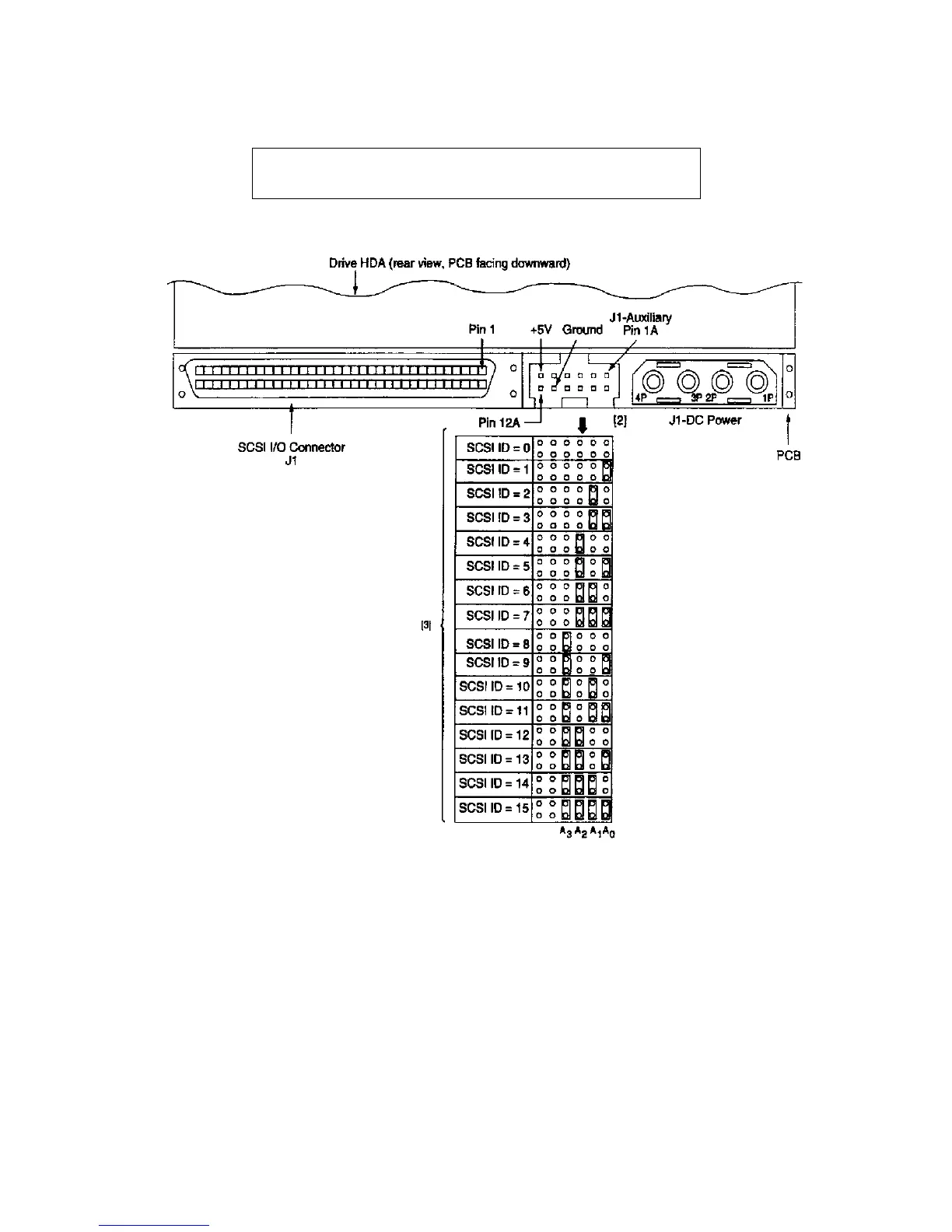
Figure8-23 shows a rear view of the J1 SCSI I/O, Auxiliary, and DC power connectors.
Figure 8-23. HP A3058A Rear View
Notes for Figure 8-22 and 8-23:
[1] Notes explaining the functions of the various jumpers on jumper header connectors J2, J1 -auxiliary and
J6 are given below in left to right order of jumper position. The term "default" means as standard OEM
units are configured when shipped from factory. "Off" means no jumper is installed; "On" means a jumper
is installed. "Off" or "On" underlined is factory default condition.
[3] Either jumper plugs in one of the patterns shown or external circuitry can be used to establish Drive I D.
The drive uses headers J6 or J1 -auxiliary for drive ID determination only during a 250 ms initialization
period following power-on or after a drive reset. During this initialization period, the drive control logic
NOTE
Use the JI position for setting the SCSI ID.

 Loading...