The Development Library 6-15
1 Type: 9=Label 2=Constant
for labels: 5 Address of label
for constants: 16 Value of constant
]
5 Number of source->code associations
n*[
5 Offset in code (this list is sorted by offset)
2 Number of link this instruction comes from
5 Character offset in link where this instruction starts
]
Notes:
• If the source string is unnamed, i.e. in TEMPOB, the number of links is 00001 and the number of
characters is 00, immediately followed by the symbol table.
• The label symbol table is supposed to be an *offset* table. However the current MASD may sometimes
place *addresses* into this table. The “associations” table correctly contains offsets.
This instruction is intended for the case where someone decides to create a source level debugger.
4.2 Saturn ASM mode
This section is only applicable to the Saturn ASM mode.
4.2.1 CPU architecture
This section purpose is to make experienced ASM programmers familiar with the Saturn architecture, not to teach
anyone to program in Saturn ASM.
The Saturn CPU has 12 main registers:
A, B, C, D, R0, R1, R2, R3 and R4 are 64 bits register (see description bellow),
D0 and D1 are 20 bits pointers (you can only access memory through them, the Saturn is a little endian),
PC, 20 bit program counter.
In addition, there are 16 flags ST0 to ST15 (12-15 being reserved for the system) 1 bit register accessible separately, a
carry that is set when operation overflow or tests are validated and can be tested using the GOC (Go On Carry) and
GONC (Go On No Carry) jump instruction, a decimal/hexadecimal mode (SETHEX and SETDEC) that affects
the way + and – instructions on the A, B, C and D register works (default Is HEX), and a 8 level return stack for
GOSUBs (and RTN).
4.2.1.1 64 bits register
Most operations on 64 bits register will act on a specific “field”. A field is a division in a 64 bit register.
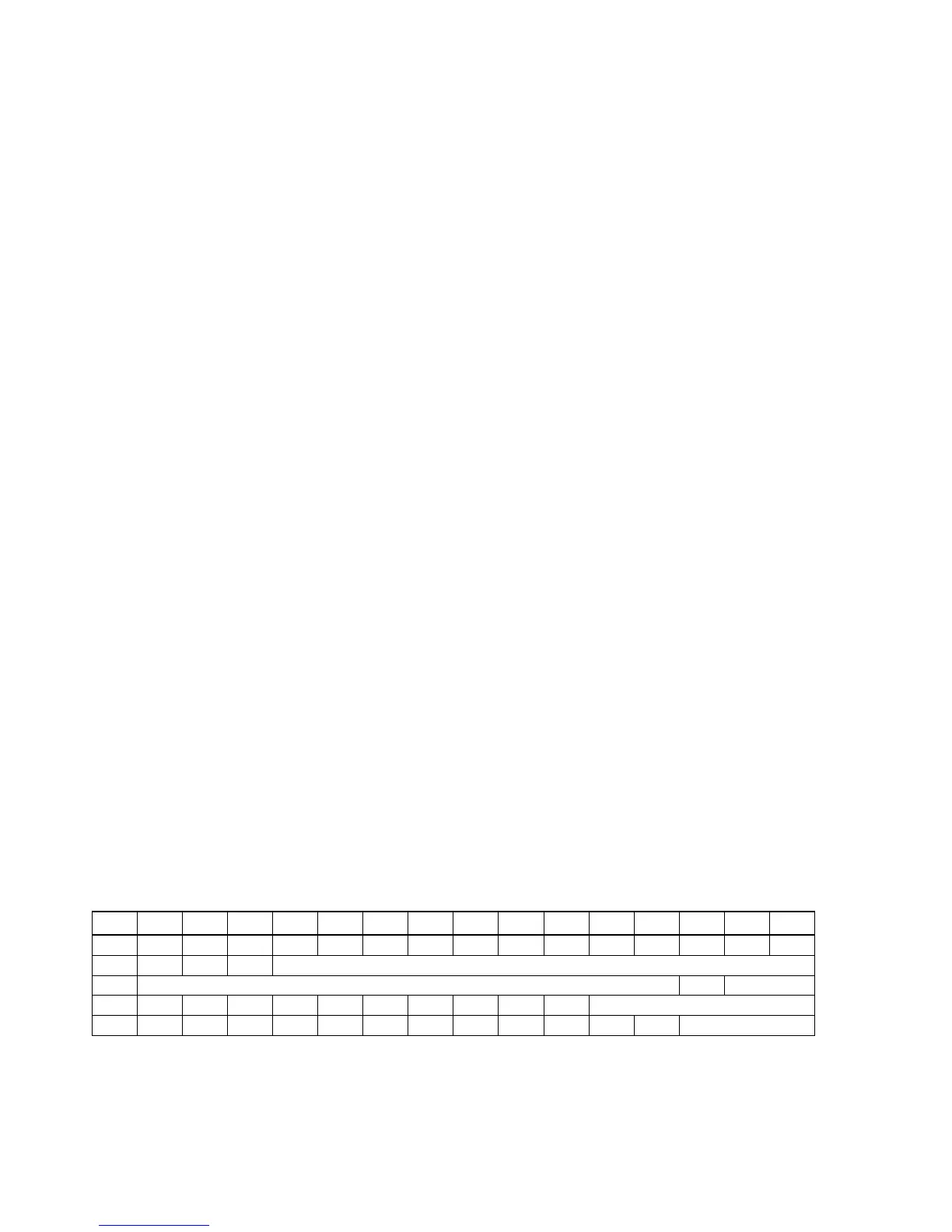
If this represents the 16 nibbles of a 64 bit register, the fields cover the register as follows:
F
E D C B A 9 8 7 6 5 4 3 2 1 0
P
WP
S M XS B
A
X
The P field location depends of the value of the 4 bit P register (ie: you can move it), and so does the WP field.
Please look at the instruction set to see what instructions are available to the programmer.
I usually write “Rf” to indicate a register (uppercase) and a field (lowercase) as in
Bo.
In addition, in the new simulated Saturn architecture, 7 new fields F1 to F7 have been introduced.