Model 5340A
Maintenance and Service
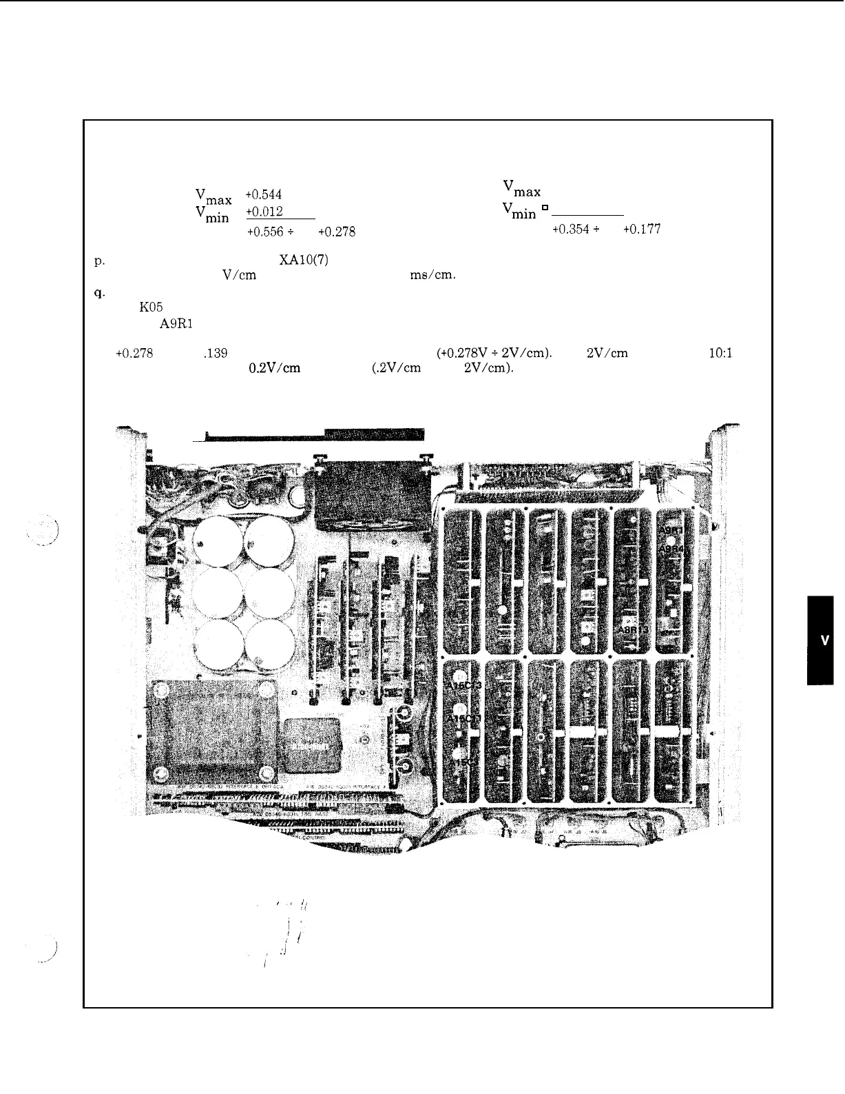
Figure 5
-
2. Adjustment Procedures (Continued)
0.
P.
q.
r.
S.
Calculate the average value of the two voltages measured in steps n and
o
above by finding the algebraic
sum
of
the voltages in step n and in step
o
and dividing by 2.
Example
1:
Vmax
=
t0.544 volts
Example
2:
Vmax
=
0.456
volts
vmin
=
+0.012
volts
Vmin
-
0.102
volts
t0.556
+
2
=
+0.278 volts
+0.354
+
2
=
+0.177 volts
Move oscilloscope probe to
XAlO(7)
(T.L. Control). Change oscilloscope controls:
Channel
A
to
0.2
V/cm dc coupled, SWEEP to 5 ms/cm.
Adjust the oscilloscope Channel
A
position
so
zero volts dc
is
at
the center
of
the screen.
Set
KO5
switch to UNLOCK.
Adjust
A9R1
(OFFSET)
so
that the wave form display
is
symmetrical about the value calculated in step
p.
For Example
1,
the ramp should be centered at t0.278 volts. Since the center
of
the screen is
0
volts,
+0.278 volts
is
.139
cm above the center
of
the screen (+0.278V
+
2V/cm). The 2V/cm
is
due to the
1O:l
divider probe and the O.ZV/cm sensitivity (.2V/cm x
10
=
2V/cm).
5
-
7