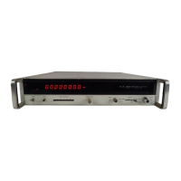
Model 5340A
Manual Changes and Options
CHANGE
5
Table 6
-
1, Replaceable
Parts:
Change A3CR5 and CR6 to 1901
-
0535, Diode:Hybrid Hot Carrier, 28480,1901
-
0535.
Change
A20C3 to 0140
-
0209 C:FXD Mica
5
pfd 5%, 500VDCW, 28480,0140
-
0209.
Change
A20C3 to
5
pfd.
Figure 8
-
27, A20 Schematic Diagram:
CHANGE
6
Table 6
-
1, Replaceable Parts:
Delete listing for
AlA5 (05340
-
6007) Filter Assy and all associated parts (AlA5A1, etc.).
Delete listing for
A2A5 (05340
-
60078) Filter Assy and all associated parts (A2A5A1, etc.).
Delete
AlA5 and AlA5A1 from schematic. Show
+
and
-
5
volt lines connected directly to
AlA2.
Delete A2A5 and A2A5A1
from
schematic. Show
+
and
-
5
volt lines connected directly to
A2A2.
Figure 8
-
7, A1 Schematic Diagram:
Figure
8
-
8,
A2 Schematic Diagram:
Table 6
-
1, A6 Replaceable
Parts:
Change A6 series number 1236A.
Change A6R13 to 0757
-
0938 R:FXD FLM 3.9K ohm
2%
1/8W,
28480,0757
-
0938.
Change
A6R15 to 0757
-
0946 RFXD FLM
8.2K
ohm 2%
1/8W,
28480, 0757
-
0946.
Change
A6R26 to 0698
-
8128 RFXD COMP 220 ohm
5%
1/8W, 01121, BB2215.
Change A6R27 to 0698
-
5075 R:FXD COMP 130 ohm
5%
1/8W, 28480, 0698
-
5075.
Change
A6R13 to 3900 ohms, A6R15 to 5600 ohms, A6R26 to 220 ohms, and A6R27 to 130
ohms.
Change
A2A4C3 to 0160
-
2150, C:FXD MICA
33
PF
5%,
28480,0160
-
2150.
Change
A2A4R4 to 0757
-
0180, RFXD
MET
FLM 31.6 ohm
1%
1/8W, 28480,0757
-
0180.
Change
A2A4 board series number to 1220A.
Figure 8
-
12, A6 Schematic Diagram:
Table 6
-
1, A2 Replaceable
Parts:
CHANGE
7
Table
6
-
1,
A10 (05340
-
60008)
Parts
List
Change Series
No.
to
1252A
Change AlOR8 to 0698
-
4433 RFXD 2260 OHM
1%
1/8W,
28480, 0698
-
4433
Delete
A10R25 and description
Table 6
-
1, A22 (05340
-
60016)
Parts
List
Change Series
No.
to
1236A
Change A22Q13 to Q16 to 1854
-
0009
Change
A22R36 to R39 to 0683
-
6215 620 ohms
Change
A22R30 to to 0683
-
3305 R:FXD COMP 330 OHM
5%
1/4W, 01121, CB33056
Change A22Q17 to 1854
-
0092
Delete
A22Q21, A22R54, and A22R55 and their descriptions
Change
A22U9 to 5088
-
7001
Figures 8
-
16 and
8
-
18
A10 and A12 (05340
-
60008) schematics:
Change
A10R8 to 2260 ohms.
Change
A10R25 200
ohm
potentiometer (L2, C5, and R8 are tied together).
Change series no. to
1236A
Change A22R30 to
33
ohms
Change
A22R36 to R39 to 2700 ohms
Replace component
kocator with Figure
7
-
1
Delete A22Q21, A22R54, and
R55
Figure 8
-
29, A22 Schematic Diagram:
I
CHANGE
8
J
Table
6
-
1,
A10 Replaceable Parts:
Change
AlOC3 to 0160
-
2671, C:FXD MYLAR
O.1pF
5%
80VDCW, 56289, 192P1045R8-PTS
Change A10L3 to 9100
-
2278, CO1L:FXD MOLDED 150
pH
lo%,
82142,09-A151K
7
-
3

 Loading...