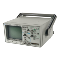
Figure 29 shows the first case, where you might trigger the analyzer by using
the trigger output of an emulator. Figure 30 shows the second case, using an
oscilloscope probe to route the signal to the external trigger input.
Connections for External Trigger from an Emulator
Measure time
Save/Recall
Entry
LOGIC ANALYZER
54620A
16 CHANNEL 500 MSa/s
STORAGE
TRIGGER
HORIZONTAL
CHANNEL
INPUTS
Line
Time/Div
Select
Trigger out
Delay
Position
Ext trigger in
GND
GND
GND
GND
Vectra
Figure 29
Making Analyzer Measurements
Extending trigger capabilities
105

 Loading...