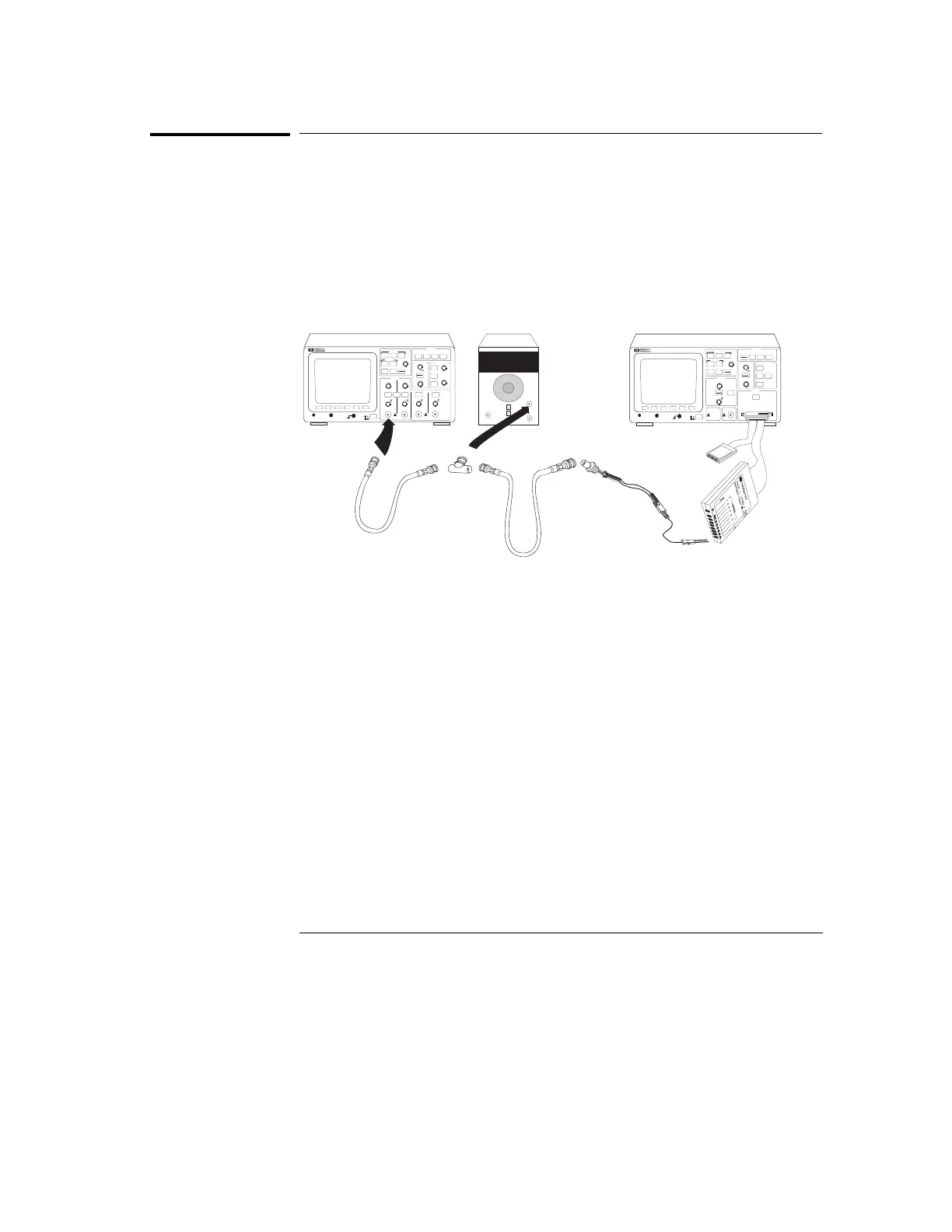
Step 1. To connect the logic analyzer
1
Using the 1-by-2 test connector and a BNC cable assembly, connect
channel 0 to one side of the BNC Tee.
2
Using a second BNC cable, connect the oscilloscope to the other side
of the BNC Tee.
3
Connect the BNC Tee to the Mark output of the time mark generator.
Time Interval Accuracy Setup
HP 54600
Measure
Save/Recall
54602A
OSCILLOSCOPE
STORAGE
TRIGGER
HORIZONTAL
VERTICAL
Line
Time/Div
Volts/Div
Volts/Div
1X
3
Delay
Position
Position
Position
Position
2Y
4Z
!
!
TG 501A
(or equivalent)
1
3
2
4
±
Measure time
Save/Recall
Entry
LOGIC ANALYZER
54620A
16 CHANNEL 500 MSa/s
STORAGE
TRIGGER
HORIZONTAL
CHANNEL
INPUTS
Line
Time/Div
Select
Trigger out
!
Delay
Position
Ext trigger in
!
!
Channels 8-15
Channels 0-7
tintnew.cdr
100ns
Figure 57
Testing, Adjusting, and Troubleshooting the Analyzer
Step 1. To connect the logic analyzer
174