To make the test connectors
The test connectors connect the logic analyzer to the test equipment.
Table 8 Materials Required
Description Recommended Part Qty
BNC (f) Connector HP 1250-1032 2
Berg Strip, 8-by-2 1
Berg Strip, 1-by-2 1
100
Ω
1% resistor HP 0698-7212 2
Jumper wire
1
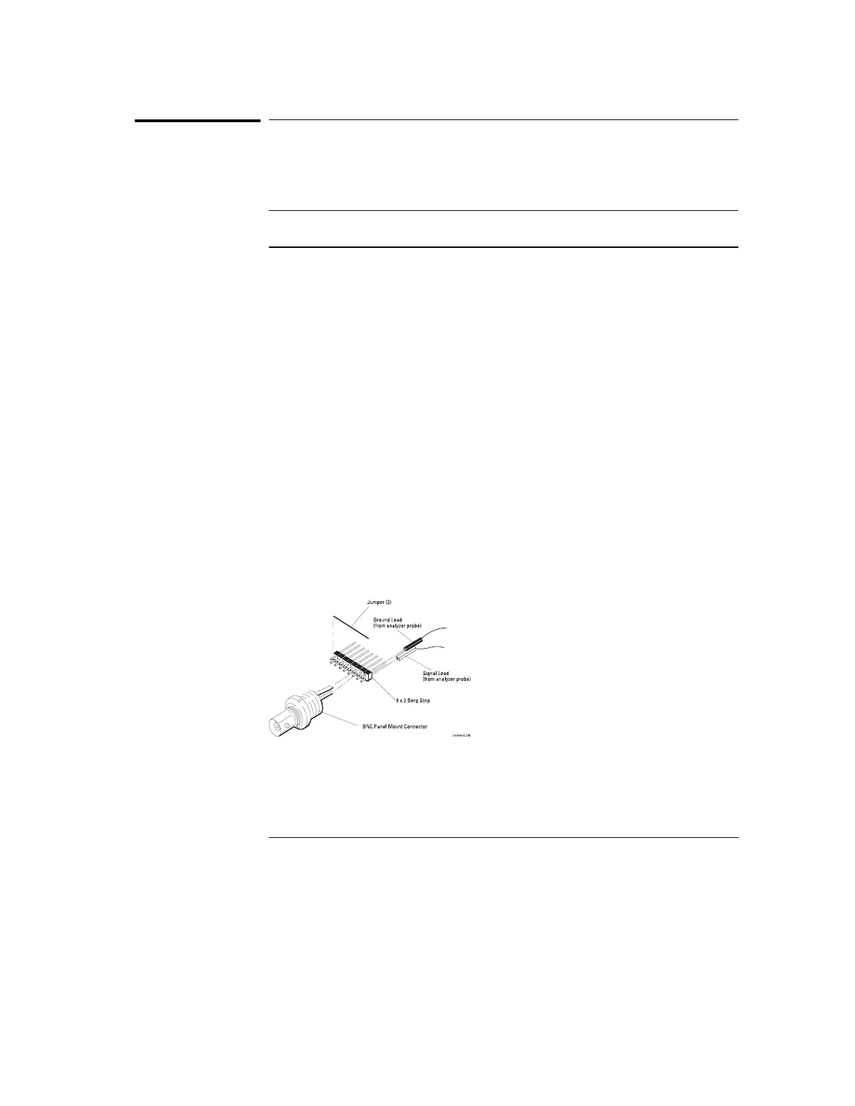
Build the first test connector using a BNC connector and an 8-by-2
section of Berg strip.
a
Solder a jumper wire to all pins on one side of the Berg strip.
b
Solder a jumper wire to all pins on the other side of the Berg strip.
cc
Solder the center of the BNC connector to the center pin of one row
on the Berg strip.
d
Solder the ground tab of the BNC connector to the center pin of the
other row on the Berg strip.
8-by-2 Connector Setup
Figure 52
Testing, Adjusting, and Troubleshooting the Analyzer
To make the test connectors
156