Step 2. To connect the logic analyzer
1
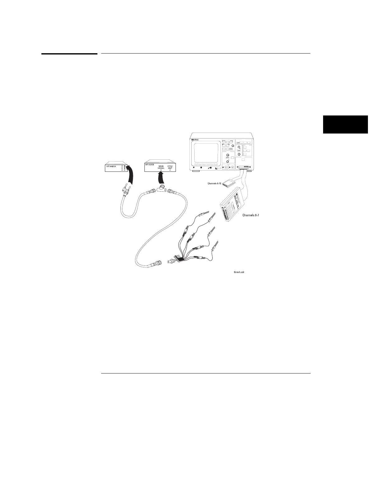
Using the 8-by-2 test connector and BNC cable assembly, connect
channels 0-7 to one side of the BNC Tee.
2
Using a BNC-banana cable, connect the voltmeter to the other side of
the BNC Tee.
3
Connect the BNC Tee to the Main Signal output of the function
generator.
Threshold Test Setup
Measure time
Save/Recall
Entry
LOGIC ANALYZER
54620A
16 CHANNEL 500 MSa/s
STORAGE
TRIGGER
HORIZONTAL
CHANNEL
INPUTS
Line
Time/Div
Select
Trigger out
Delay
Position
Ext trigger in
Figure 56
Testing, Adjusting, and Troubleshooting the Analyzer
Step 2. To connect the logic analyzer
171

 Loading...


