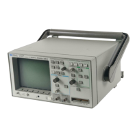
Trigger Output
The trigger output is pulsed when the analyzer’s trigger condition is satisfied
and the analyzer begins acquiring data. Thus, it can be used to trigger an
external measurement system or other device. For example, you might want
to use the trigger output to trigger an oscilloscope, or even to trigger another
HP 54620A/C for complex problems requiring more channels. The trigger
output signal cannot be viewed on the waveform display.
A rising edge at the trigger output indicates that the trigger condition was
satisfied. The trigger output occurs shortly after the trigger data occurs,
typically 85 ns. Because of the overhead of acquisition and display, the
trigger is not driven every time the trigger condition occurs in the target
system. It is driven as often as is practical. If the logic analyzer is in Run
mode (continuous acquisition), you can speed repetition of the trigger output
by pressing the Run/Stop key to stop acquisition.
You can also use the trigger output for single-shot events. When you press
the Single key, the analyzer will drive the trigger output high when the
trigger condition is found. The trigger output will not go low again until
another acquisition begins; the signal is driven low while the analyzer
searches for the trigger condition. If you stop the analyzer before the trigger
is found, there will not be a trigger output.
Figure 31 shows the connections required for triggering an oscilloscope from
the HP 54620A/C.
Connections for Triggering an Oscilloscope
Measure time
Measure
Save/Recall
Save/Recall
Entry
LOGIC ANALYZER
54620A
16 CHANNEL 500 MSa/s
54602A
OSCILLOSCOPE
STORAGE
STORAGE
TRIGGER
TRIGGER
HORIZONTAL
HORIZONTAL
CHANNEL
VERTICAL
INPUTS
Line
Line
Time/Div
Time/Div
Select
Volts/Div
Volts/Div
Trigger out
1X
3
Delay
Delay
Position
Position
Position
Position
Position
Ext trigger in
2Y
4Z
GND
GND
GND
GND
1
3
2
4
±
Figure 31
Making Analyzer Measurements
Extending trigger capabilities
107

 Loading...