The trigger point is off-screen to the right—that is why the solid triangle is at
the right edge of the graticule. If you now stop and pan the display back by
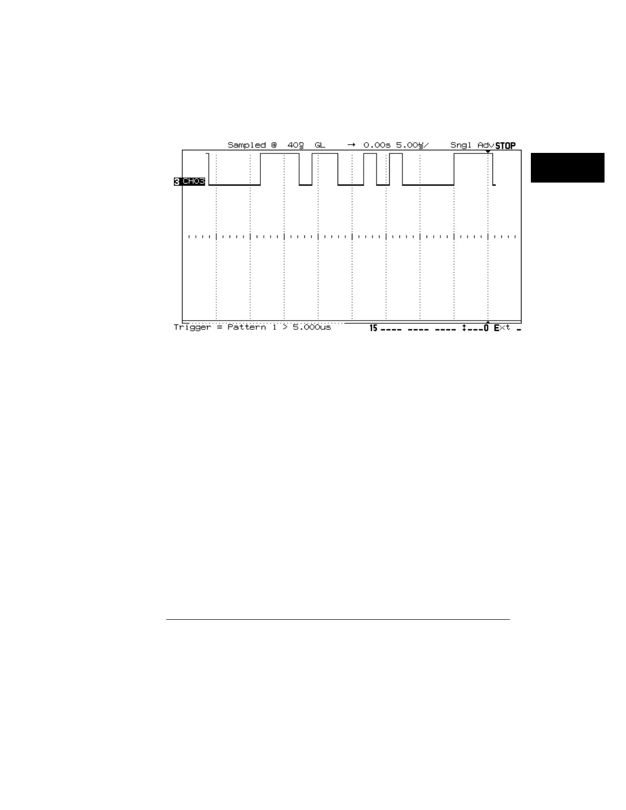
setting the delay to 0 µs, the result looks like the following:
Panning the Display to View the Trigger Point
Here, the trigger point is in memory. Note the memory bar position and that
the delay value is 0. See chapter 7, “Performance Characteristics,” for more
information on the specific limits available under delayed sweep.
Measurement Functions
The analyzer’s single- and dual-channel measurement functions cannot be
more accurate than the current sampling period. Suppose that you are trying
to measure a skew value believed to be in the range of 5 to 10 ns, using the
channel-to-channel delay function. If you have the sweep speed set to
5 µs/div, the current sampling period is 40 ns. Thus, you will see a
measurement result of either 0 ns or 40 ns, depending on where the
waveform edges fall in relation to sampling.
The solution is to compare the current sample period against the expected
measurement results, and change to lower Time/Div values (faster sweep
speeds) if necessary to achieve the desired accuracy. In the example above,
to accurately measure the value, you need to select a sweep speed of at least
500 ns/div or faster. Remember, however, that all measurements require that
the events being measured be displayed on screen.
Figure 41
Ensuring Accurate Measurements
Time base and Acquisition
137

 Loading...


