Source Operator and
Parameters
Pattern/Edge
Pattern 1 Then L on channels 2, 1, and 0, others don’t care
Pattern 2 N/A L on channels 2 and 1, H on channel 0,
others don’t care
Example
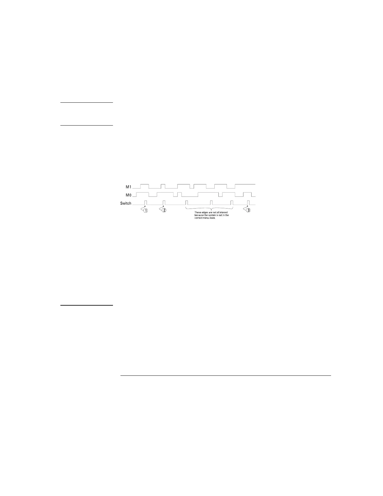
Suppose you have a microcontroller-based system that consistently fails the
third time you push a particular front-panel switch when a particular system
display menu is active. If M1 and M0 represent the particular data lines that
indicate menu state, and the system menu in question is active when both
these lines are high, then figure 19 represents a combination of events
leading to the failure condition.
System Failure on Third Keystroke
If input lines M1, M0, and SWITCH are connected to input channels 2, 1, and
0 respectively, the following trigger configuration will trigger the analyzer
when the failure condition occurs. The occurrence count is incremented each
time the edge occurs when the associated pattern is true.
Source Operator and
Parameters
Pattern/Edge
Pattern 1 & Edge 1 Occurs 3 times H on channels 2, 1 in Pattern 1; Rising Edge
on channel 0 in Edge 1
Figure 19
Making Analyzer Measurements
To define an advanced trigger
78
 Loading...


