Removal and Replacement
Procedures
55
4.3 System Board
This section provides additional information about the system board.
• Section 4.3.1 “System Board Components”
• Section 4.3.2 “System Board Architecture”
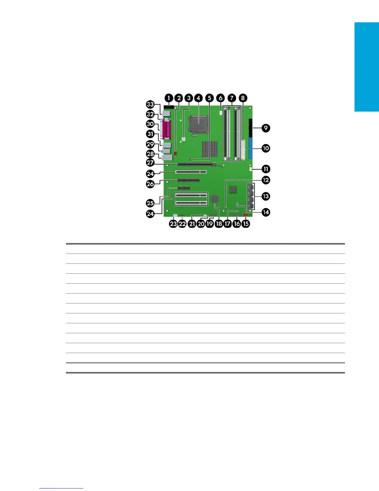
4.3.1 System Board Components
The following illustration shows the system board connectors and sockets on the HP xw4300 Workstation.
Table 4-8 System Board Components
1 Second serial port adapter 13 Serial ATA ports 25 PCI
2 Rear fan 14 Clear CMOS button 26 PCI Express x1
3 Processor power connector 15 Front chassis fan 27 PCI Express x8’ (x4)
4 Processor 16 Front control panel 28 PCI
5 Solenoid hood lock 17 Password jumper 29 PCI Express x16
6 Processor fan connector 18 Battery 30 Network/USB
7 Memory module sockets 19 Front USB 31 Audio
8 Main power 20 Hard disk activity LED 32 USB
9 Diskette drive connector 21 Chassis speaker 33 Parallel
10 Primary IDE* connector 22 Front audio 34 Serial
11 Chassis intrusion switch 23 Auxiliary audio 35 Keyboard/mouse
12 Boot block jumper 24 CD-ROM audio
*The Primary IDE connector is only used for optical drives.
 Loading...