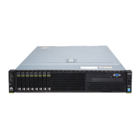
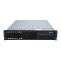
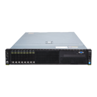
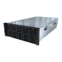
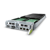
Table 2-5 Hard disk layout of the RH8100 V3 with the FM-D
HDD0 HDD2 HDD4 HDD6
HDD1 HDD3 HDD5 HDD7
Figure 2-9 describes the mapping between memory board numbers and CPU
socket numbers.
Figure 2-9 Mapping between memory board numbers and CPU socket numbers
Rear Panel
Figure 2-10 shows the RH8100 V3 rear panel.
RH8100 V3 Server
User Guide 2 About the RH8100 V3
Issue 30 (2019-12-19) Copyright © Huawei Technologies Co., Ltd. 16
 Loading...
