EasyManuals Logo

Hypertherm Powermax65 SYNC Troubleshooting Guide

Hypertherm Powermax65 SYNC
180 pages
To Next Page IconTo Next Page
To Previous Page IconTo Previous Page
Page #109 background imageLoading...
Page #109 background image
Do System Tests to Identify Defective Components
5
Powermax65/85/105 SYNC Troubleshooting Guide 810430 109
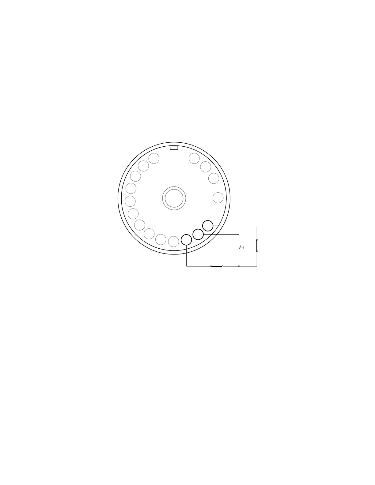
7. Do a check for continuity on the torch wires, as follows:
a. Remove the left side of the torch shell.
b. Do a check for continuity between the blue wire and pin 5 (BLU) in the torch connector.
c. Do a check for continuity between the orange wire and pin 7 (ORG) in the torch connector.
8. Do both torch wires have continuity?
If yes, replace the cap-sensor switch.
If no, replace the torch lead.
Figure 26 – Torch connector pins
BLK
BLK
1
2
3
4
5
BLU
6
VIO
7
ORG
8
BLK
9
BRN
10
GRY
11
YEL
12
WHT
13
RED
14
15
16
17
Cap
Start
Torch-disable switch

Table of Contents

Other manuals for Hypertherm Powermax65 SYNC

Questions and Answers:

Question and Answer IconNeed help?

Do you have a question about the Hypertherm Powermax65 SYNC and is the answer not in the manual?

Hypertherm Powermax65 SYNC Specifications

General IconGeneral
BrandHypertherm
ModelPowermax65 SYNC
CategoryWelding System
LanguageEnglish

Related product manuals