Do System Tests to Identify Defective Components
Powermax65/85/105 SYNC Troubleshooting Guide 810430 121
7. Measure the DC voltage between pin 1 and pin 4 at the fan connector. Use extended thin meter
points to get the voltage reading on the external side of the power PCB. Refer to Figure 34 on
page 122. Is the voltage approximately 48 VDC (±2.4 VDC)?
If yes, replace the fan.
If no, continue with the next step.
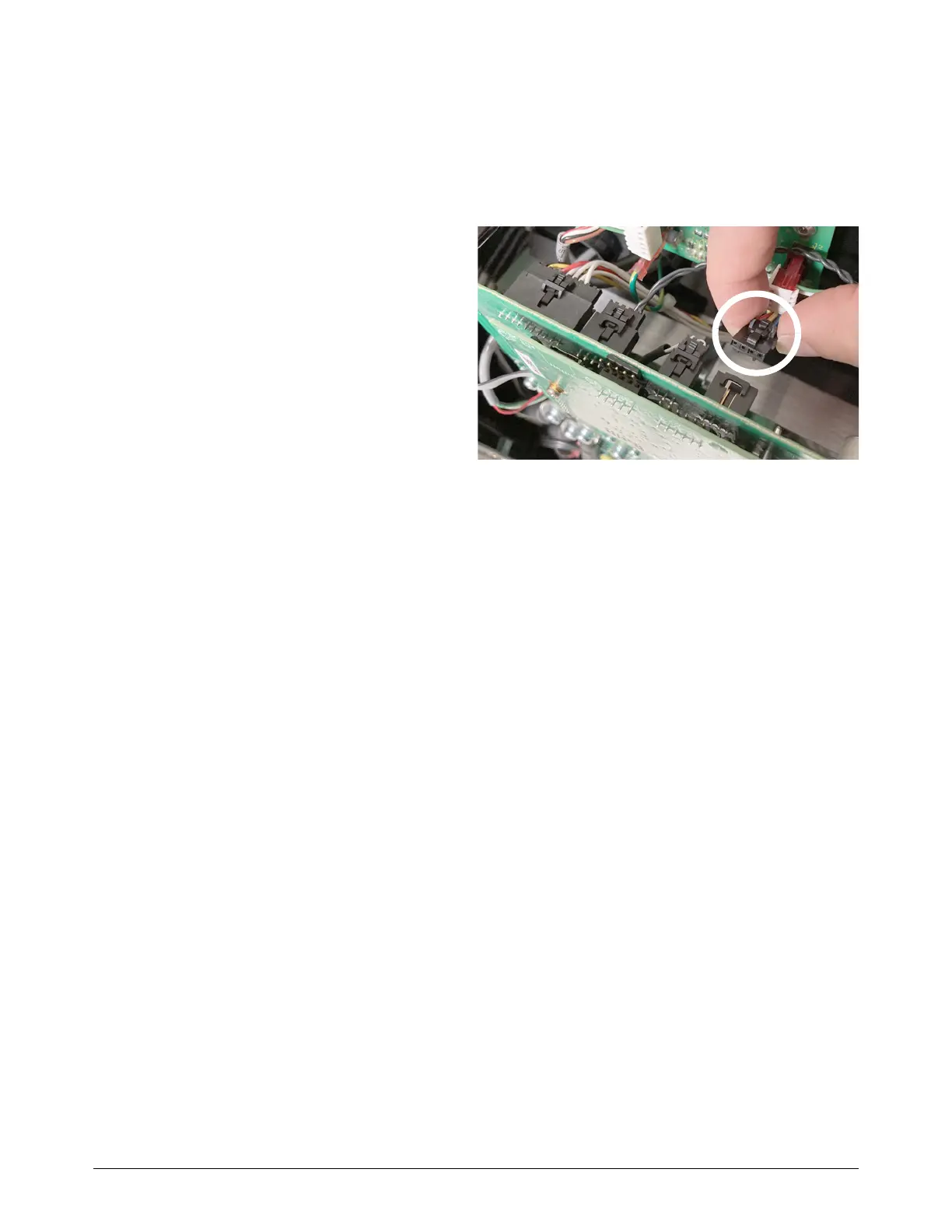
8. Disconnect the fan from the power
PCB.
9. Measure the voltage again between
pin 1 and pin 4 at the fan receptacle
on the power PCB. Is the voltage
approximately 48 VDC (±2.4 VDC)?
If yes, replace the fan.
If no, do Test 5 – Flyback circuit
(DC minor voltages) on page 94.