Do System Tests to Identify Defective Components
Powermax65/85/105 SYNC Troubleshooting Guide 810430 129
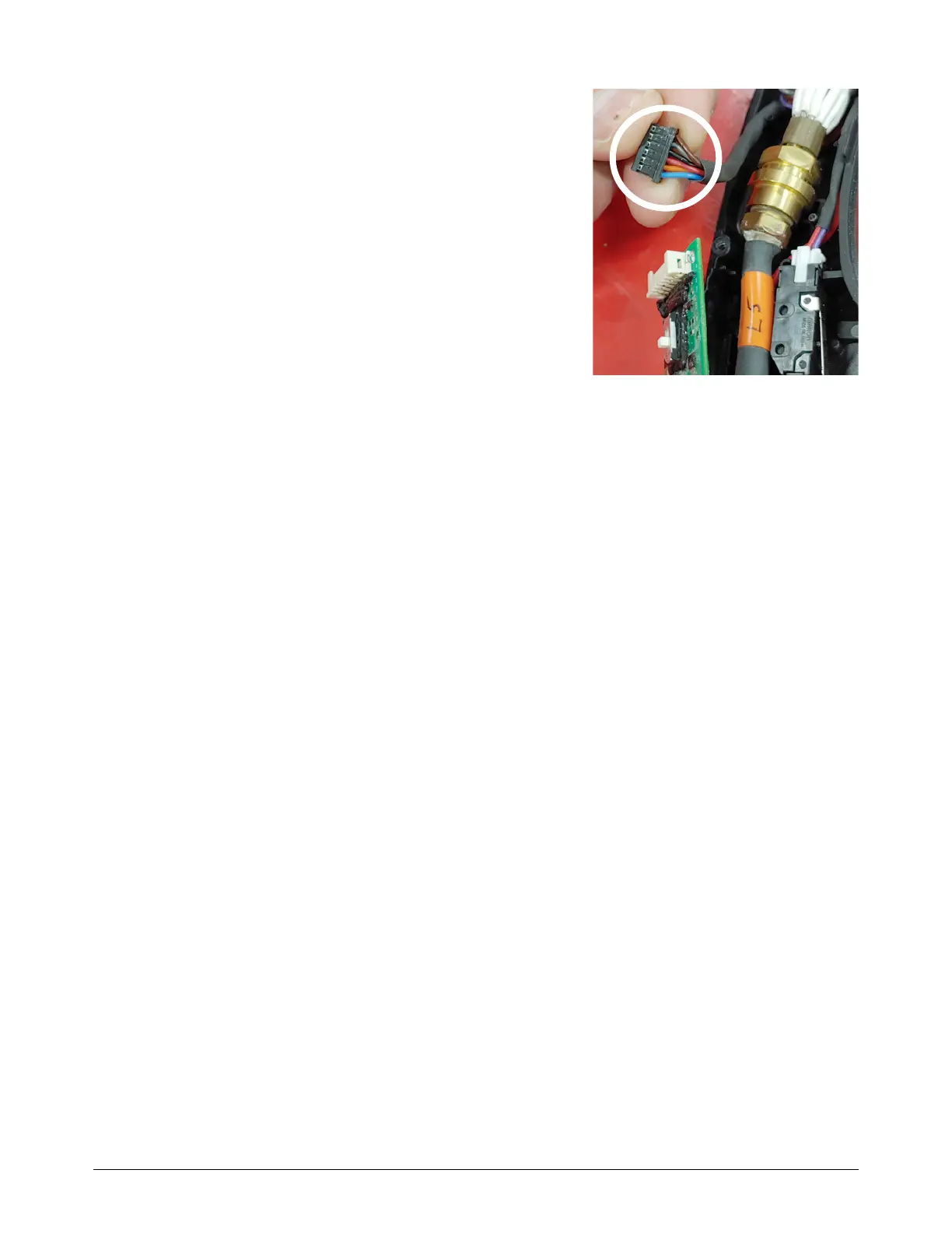
8. Disconnect the torch lead connector from the torch
PCB.
9. Measure the voltage again between pin 3 (black wire)
and pin 5 (orange wire). This time, put the multimeter
leads directly in the sockets for pin 3 and pin 5. Is the
voltage approximately 18 VDC?
If yes, replace the power PCB.
If no, continue with the next step.
10. Connect a different SmartSYNC torch to the plasma
power supply that is known to operate correctly. Do
you continue to get the 0-98-2 fault?
If yes, replace the power PCB.
If no, there is a possible problem with the original torch. Continue with the next step.
11 . Connect the original SmartSYNC torch to the plasma power supply. Is the torch a hand torch or
a mechanized torch?
Hand torch: Are any LEDs on the torch PCB illuminated or flashing?
If yes, replace the torch PCB.
If no, replace the torch lead.
Mechanized torch: Replace the torch PCB. If the 0-98-2 fault does not go away, replace
the torch lead.
If communication faults continue, examine the DSP PCB. Continue with the next step.
12. Disconnect the DSP PCB from the power PCB. Carefully remove the conformal coating from
the pins, if necessary. Too much of this coating can prevent a good connection with the power
PCB.
13. If the problem continues, replace the DSP PCB.
14. If the problem continues after a new DSP PCB is installed, replace the power PCB.