Do System Tests to Identify Defective Components
Powermax65/85/105 SYNC Troubleshooting Guide 810430 95
Table 7
5. Is the 48 VDC measurement for the fan correct?
If yes, continue with the next step.
If no, disconnect the fan connector from the power PCB. Measure the voltage again from
pin 1 to ground. Is the voltage correct now?
If yes, replace the fan.
If no, continue with the next step.
6. Are the 48 VDC, 24 VDC, and 5 VDC measurements for the solenoid valve electronic regulator
all correct?
If yes, continue with the next step.
If no, disconnect the solenoid valve electronic regulator from the power PCB. Measure the
voltage again from pin 7, pin 5, or pin 4 to ground. Is the voltage correct now?
If yes, replace the solenoid valve assembly.
If no, continue with the next step.
7. Is the 3.3 VDC measurement on the power PCB correct?
If yes, continue with the next step.
If no, remove the DSP PCB from the system. Measure the voltage again from pin 4 to
ground. Is the voltage correct now?
If yes, continue with the next step.
If no, replace the power PCB.
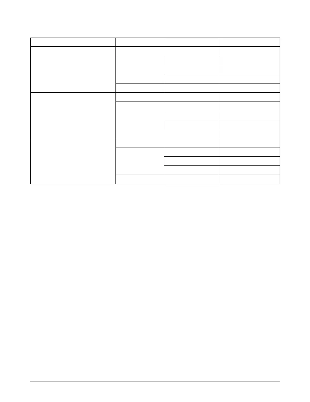
System Component Pin number to ground Correct voltage (±15%)
Powermax65/85 SYNC CSA
Fan Pin 1 on J3 +48 VDC
Solenoid valve
electronic regulator
Pin 7 on J4 +48 VDC
Pin 5 on J4 +24 VDC
Pin 4 on J4 +5 VDC
Power PCB Pin 4 on J11 +3.3 VDC
Powermax65/85 SYNC CE/CCC
Fan Pin 1 on J5 +48 VDC
Solenoid valve
electronic regulator
Pin 7 on J6 +48 VDC
Pin 5 on J6 +24 VDC
Pin 4 on J6 +5 VDC
Power PCB Pin 4 on J14 +3.3 VDC
Powermax105 SYNC
Fan Pin 1 on J1 +48 VDC
Solenoid valve
electronic regulator
Pin 7 on J6 +48 VDC
Pin 5 on J6 +24 VDC
Pin 4 on J4 +5 VDC
Power PCB Pin 4 on J15 +3.3 VDC