8.6 How to replace components
8-26
8. Maintenance and Inspection
4) Loosen the screws (2 pcs) affixing the motor cover assembly (bottom) and take off
the motor cover assembly (bottom).
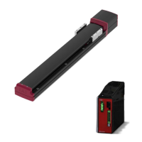
5) Take off the connectors on Motor Cable [B], Encoder Cable [C] and Brake Cable [D]
for the brake-equipped type, loosen the screws (2 pcs) at the top of the motor cover
assembly, and take off the old motor cover assembly (top).
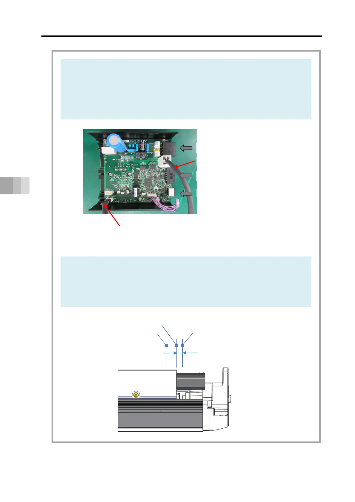
6) Loosen the coupling screw (1 pc) at the oblong hole on the top of the rear bracket,
loosen the motor unit fixing screws (4 pcs) and take off the motor unit.
7) Hold the slider at a place when Distance Lc between the slider position and the
mechanical end on the home side gets as shown in the next table.
Power I/O connector
Encoder cable [C]
(Ferrite core on PCB side)
Motor cable [B]
Teaching port
Motor power supply connector
Mechanical end
Slider position at coupling tightening
Home position
Lc
 Loading...