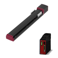
2.4 How to Install motor drive DC power supply PSA-200 ·················· 2-10
How to install, Orientation of installation ·························································· 2-10
Chapter 3 Wiring
3.1 System configuration ······························································· 3-1
3.2 Electrical specifications ···························································· 3-2
Specifications table ······················································································· 3-2
Max. units connectable to motor drive DC power supply PSA-200 ·························· 3-6
Current amperage and heat generation of motor drive DC power supply PSA-200 ····· 3-7
Selection of circuit breaker ·············································································· 3-8
Selection of leak current breaker ······································································ 3-8
I/O specifications of actuator main unit ······························································ 3-9
Status output connector for motor drive DC power supply PSA-200 ······················ 3-10
Number of connectable regenerative resistor units (Option) (Reference) ················ 3-11
Brake release method (for brake-equipped type) ··············································· 3-12
Grounding terminal Actuator main unit ·························································· 3-12
Grounding terminal motor drive DC power supply PSA-200 ································· 3-13
3.3 Connection arrangement diagram ············································ 3-14
Motor drive DC power supply PSA-200 ··························································· 3-14
Actuator main unit ······················································································· 3-16
Example for wiring actuator units and motor drive DC power supply PSA-200 ········· 3-19
3.4 Wiring connections (for connectors) ·········································· 3-22
Power supply connector ··············································································· 3-22
Connectivity between actuator units and motor drive DC power supply ·················· 3-23
Regenerative resistor unit (Option) ································································· 3-25
24 V DC power supply wiring ········································································ 3-27
PLC wiring ································································································· 3-29
Connector wiring method ·············································································· 3-30
Brake release wiring ···················································································· 3-32
3.5 Wiring connections (for cables)················································ 3-32
Power I/O cable ·························································································· 3-32
Power I/O cable connection ·········································································· 3-33
24 V DC power supply wiring ········································································ 3-34
PLC wiring ································································································· 3-36
Brake release wiring ···················································································· 3-37
Chapter 4 Operation
4.1 Basic operation ······································································ 4-1
Order to turn power on ··················································································· 4-2
Order to turn power off ··················································································· 4-2
4.2 Teaching tool connections and testing operation ··························· 4-3
Teaching pendant connection ·········································································· 4-3
ELECYLINDER test operation ········································································· 4-4
4.3 Stop position/operating conditions (AVD) setting/adjustment ············ 4-5
Stop position setting/adjustment (forward end / backward end) ······························ 4-6
Operating conditions (AVD) setting/adjustment ··················································· 4-7
4.4 I/O signals ·········································································· 4-10
I/O signal list ······························································································ 4-10
[ST0] [ST1] signals: Movement command input (backward/forward) ······················ 4-11

 Loading...