3.3 Connection arrangement diagram
3-20
3. Wiring
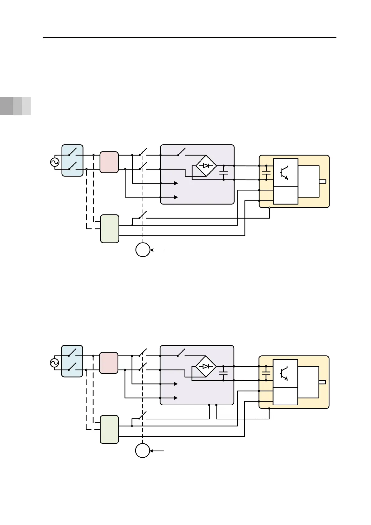
[2] Two-circuit power supply specification (Option)
Shown in the figure below is an example of wiring for a TMD2 type.
When it is required to have a drive cutoff without turning the ELECYLINDER control power
supply off, select this specification.
Unlike the pulse motor type ELECYLINDER, “B1 24 V (Drive)” Signal should be the one to
perform the stop process of an actuator. Cutting off “B1 24 V (Drive)” Signal should stop an
actuator.
In order to cut off the drive source, it is necessary to cut off the AC power on PSA-200.
[3] Two-circuit power supply specification (Option) (Connection of PSA-200 status output signal)
Shown in the figure below is an example of the wiring diagram when having the PSA-200
status output signal connected to the TMD2 type.
Basically, it behaves the same as the one shown in the figure above, however, it can
immediately stop the ELECYLINDER operation when PSA-200 cuts off the motor power
supply due to an alarm generation.
MCCB
NF
PSA-24
MC
Control with device such as stop switch
Control
Power
PSA-200
L1
L2
L1C
L2C
24 V
(control)
0 V
24 V (drive)
* STOP
Control
MOT
EC200
MCCB
NF
PSA-24
MC
Control with device such as stop switch
Control
Power
PSA-200
L1
L2
L1C
L2C
24 V
(control)
0 V
24 V (drive)
* STOP
Control
MOT
EC200
MP+
MP-
Status output
connector

 Loading...