3.3 Connection arrangement diagram
3-21
3. Wiring
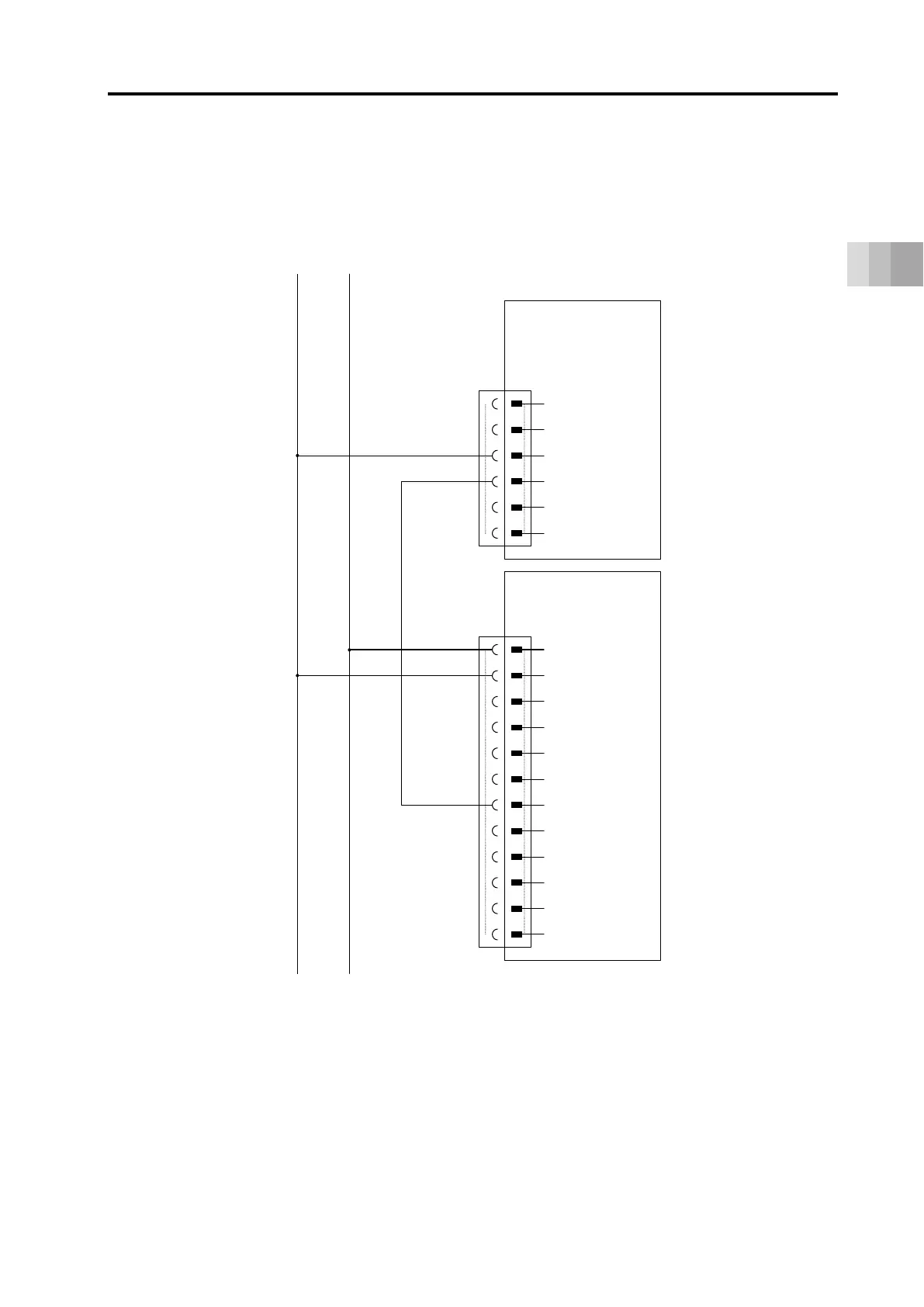
If it is required to stop the ELECYLINDER operation when the motor power supply on the motor
drive DC power supply PSA-200 gets cut off, establish the connectivity of the power supply I/O
connector and the status output connector on ELECYLINDER (TMD2 type) as shown in the
diagram below.
Motor drive DC power supply
● PSA-200
Status output connector
B1
B2
B3
B4
B5
B6
A1
A2
A3
A4
A5
A6
3
4
5
6
1
2
ELECYLINDER
(TMD2 specification)
24 V DC
0 V
PWR+
PWR-
MP+
MP-
* ALM+
* ALM-
0 V
24 V (Control)
24 V (Drive)
OUT0
OUT1
OUT2
RSV
BKRLS
IN0
IN1
IN2
RSV
Power I/O connector

 Loading...